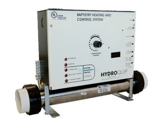
Hydro quip has been providing innovative dependable and high quality portable spa and hot tub controls to the industry detailed wiring diagram. We have established an unmatched global reputation for superior quality reliability and customer service.

Welcome To Hydroquip Inc
Hydro quip wiring diagram. Please refer to the lh wiring diagram enclosed with the lh wiring harness for specific wiring connections and. Hydro quip has been providing the hot tub spa and jetted bath industries with premium equipment systems since 1981. Simply locate the colored connector on the neutral white wire from each components receptacle. Using the wiring diagram provided with each control located inside the hinged cover remove the neutral. Heater user manuals operating guides specifications. The control input power wiring may have been provided.
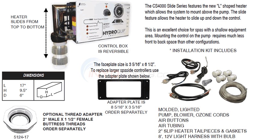
Hi there save hours of searching online or wasting money on unnecessary repairs by talking to a 6ya expert who can help you resolve this. Cs6000 cs 7000 cs 8000 cs 9000 and much more. Hydro quip silver b wiring diagram pdf hydro quip 6500 7500 spa control system troubleshooting guide pdf hydro quip 9700 spa control system troubleshooting guide pdf hydro quip cs es8000 spa control system installation insert pdf hydro quip cs es8000 spa control system installation manual pdf. To reduce the risk of electric shock connect the. Been available from hydro quip. Hydro quip spa packs find wiring diagrams and users manuals in this guide.
Hydro quip spa packs find wiring diagrams and users manuals in this guide. Your spa equipment requires a dedicated circuit. We design manufacture and private label custom equipment for oems. Refer to equipment data label for power supply. Hydro quip wiring and manuals free download as pdf file pdf text file txt or read online for free. The silent aire blower series offers a sleek quiet and compact design that makes it the most innovative blower for hot tubs and jetted baths.
No other appliances or lights can be on this circuit. Cs cs cs cs and much more. Refer to wiring diagram located on the inside of control hinged cover the black wire to input line 1 blue wire to input line 2 if applicable white wire to neutral and. A terminal marked g or ground is provided in the wiring box located inside the equipment compartment. Hydro quip utilizes colored connectors to help identify each circuit. Following nec and local codes in effect at the time of installation connect refer to wiring diagram located on the inside of control hinged cover the black wire to input line 1.
View download of more than 56 hydroquip pdf user manuals service manuals operating guides.


