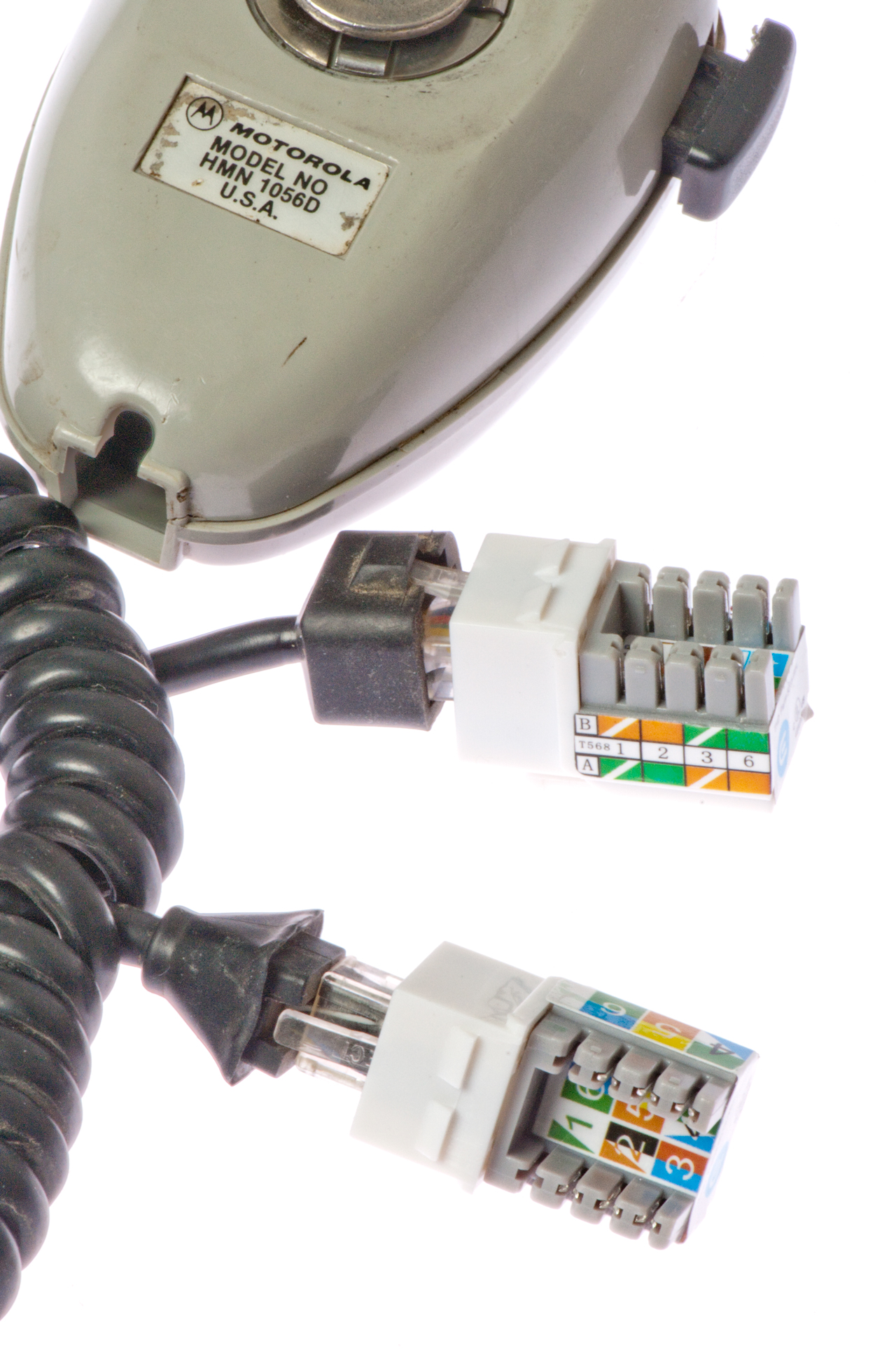
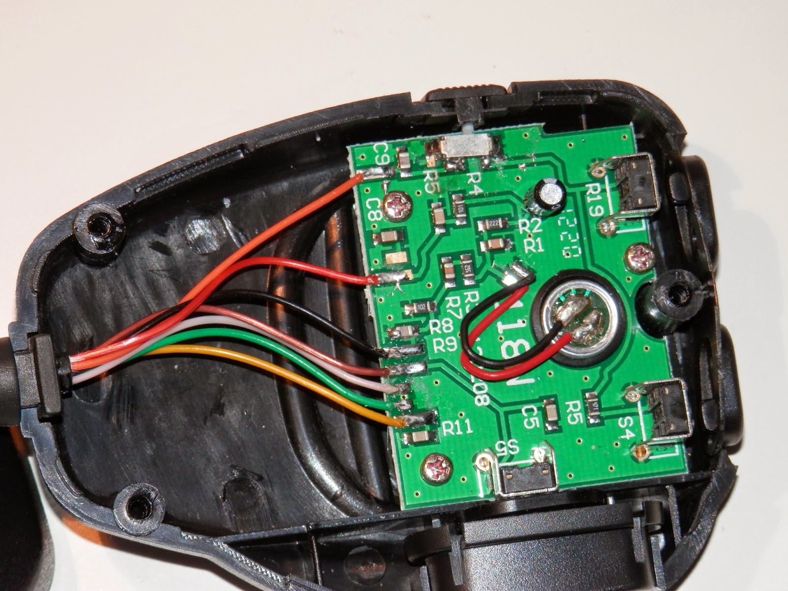
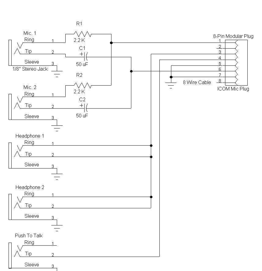
Hm 77a delta grp 281h 481h 2340h 2000h 207 2350h ex 1372 8 pin modular dtmf mic elect 706 706mk2 706mk2g hm 88a delta grp ex 1471 4 pin modular multi fx elect hm 90a 2700 grp 207h ex 1511 4 pin to 8pin mod infrared wireless elect. 8 modular type microphone connectorconnects the supplied microphone hm 103.
Heil Proset Ic
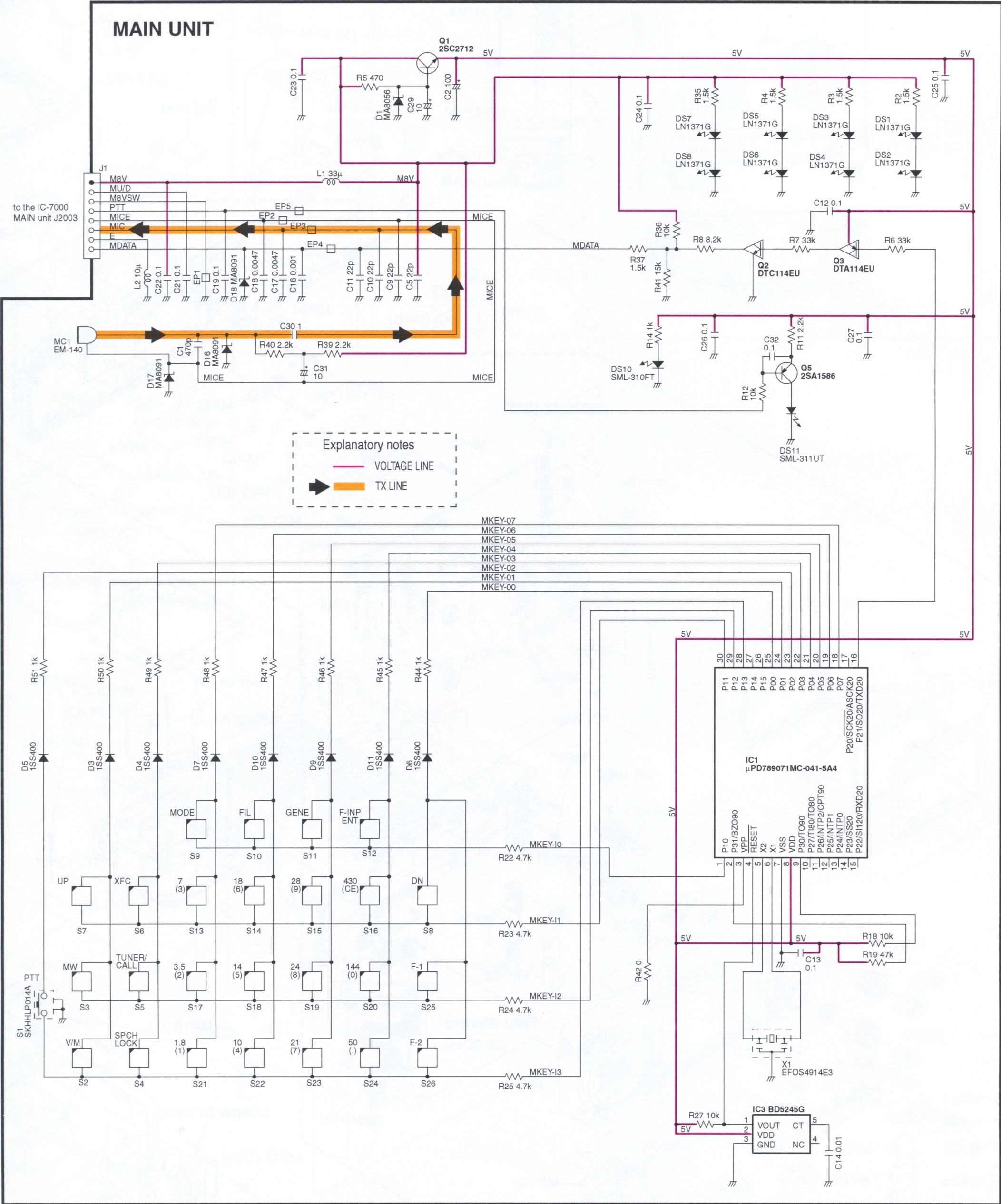
Icom 706 mic wiring diagram. This link is listed in our web site directory since tuesday feb 14 2006 and till today icom ic 706 schematic has been followed for a total of 6391 timesso far received 12 votes for a total score of 65310. Icom 78 service manual icom at 120 service manual icom at 130 at 140 service manual icom bc 72 parts list icom bc 72 schematic icom cm 60a service manual icom ds 100 service manual icom f3 f4 service manual icom ff 88 service manual icom fp 561 service manual icom gp 22 service manual icom ic 02a at e. Pin7 mic screenearth pin8 earth alinco dr605 modular plug pin1 5volt pin2 down pin3 nc pin4 ptt. Used on ic 703 ic 706 all models ic 2000 ic 2000h note. Icom america support microphone reference. On some radios pin 3 is a low level audio output 100 300mv and will not work properly with the baypac.
The main category is icom ic 706 resources that is about icom ic 706 links. Wiring color code and pinouts icom hm 103 hand mic. On these radios youll need to use the external speaker output. Icom ic 281 to mfj 1270cq turbo 30012009600 baud tnc icom 281 both ports 1200 and 9600 baud. View rj 45 connector with the locking catch away from you and contacts up. Ic 706 ic 706 mk ii ic 2000 wires.
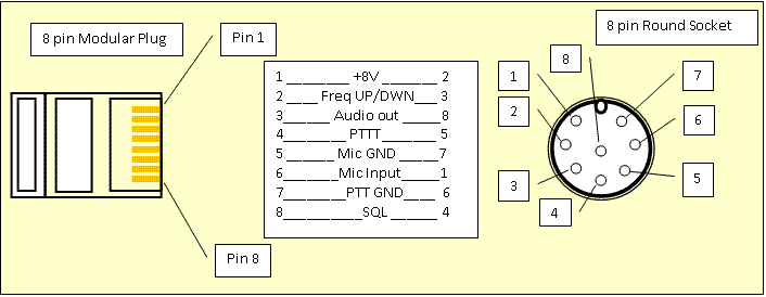
If so then nc. Blk pin 7 gnd red pin 4 ptt grn pin 3 rx audio yel pin 6 mic note. Icom ic 281 to timewaveaea pk 96 two ports 1200 and 9600 baud pk 88 8 pin to icom 8. Af hfvhfuhf transceiver i706mkg rit sub menu f. Yel pin 1 mic rj 45 connector models. This will orient pins as shown in diagram below.
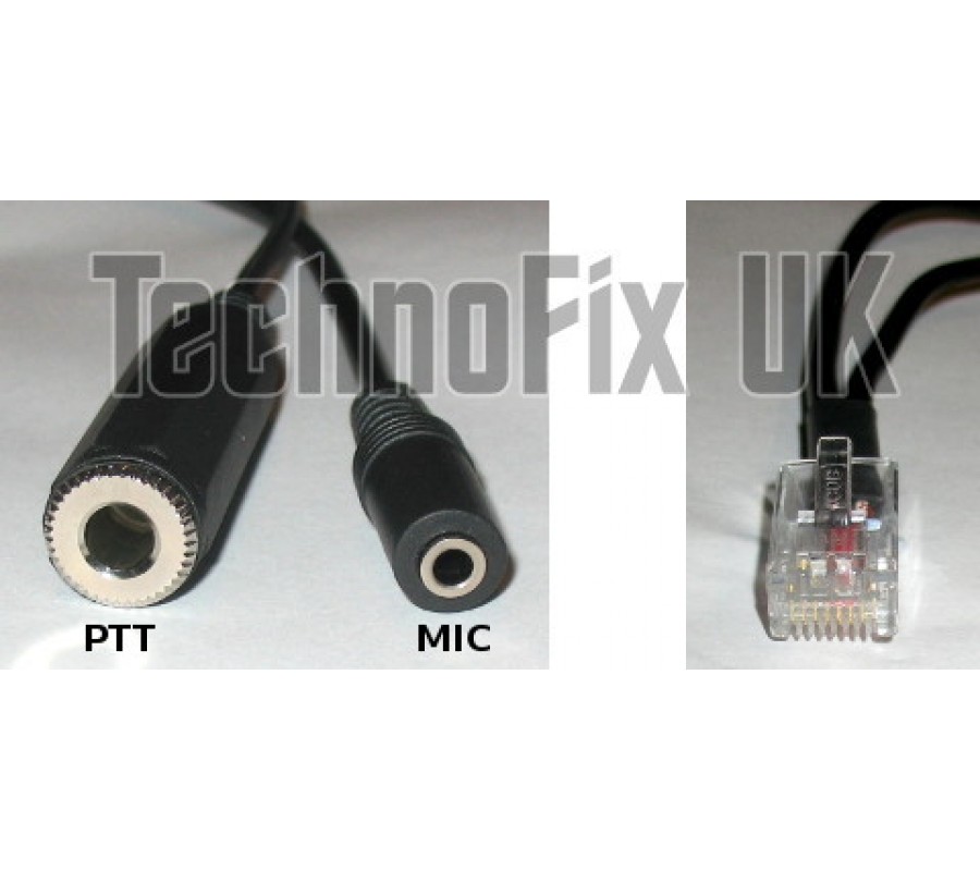
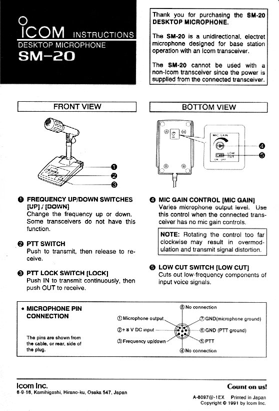
The optional opc 589 can be used to connect an 8 pin microphone such as the sm 8 or sm 20 if desired. Icom ic 706 to rj 45 mic port for 1200 baud operation. Icom ic 2100 to mfj 1270c. Resources listed under mic wiring category belongs to technical reference main collection and get reviewed and rated by amateur radio operators. A microphone connector is also available on the rear 1. Icom ic 281 rj45 mic io to mfj 1270c or x 1j4 thenet node.
Pin1 mic dc volts for icom only microphone pin2 8volts 10ma to avoid damaging the regulator do not short to ground pin3 updown pin4 squelch pin5 ptt pin6 ground pin7 mic screenearth. Links to microphone wiring diagrams category is a curation of 30 web resources on electro voice 664 wiring kenwood pin connectors microphone connections by g4wpw. Icom diagrams schematics and service manuals download for free. Hm 103 see lower diagram below pin 1 8 vdc red may not be present.

