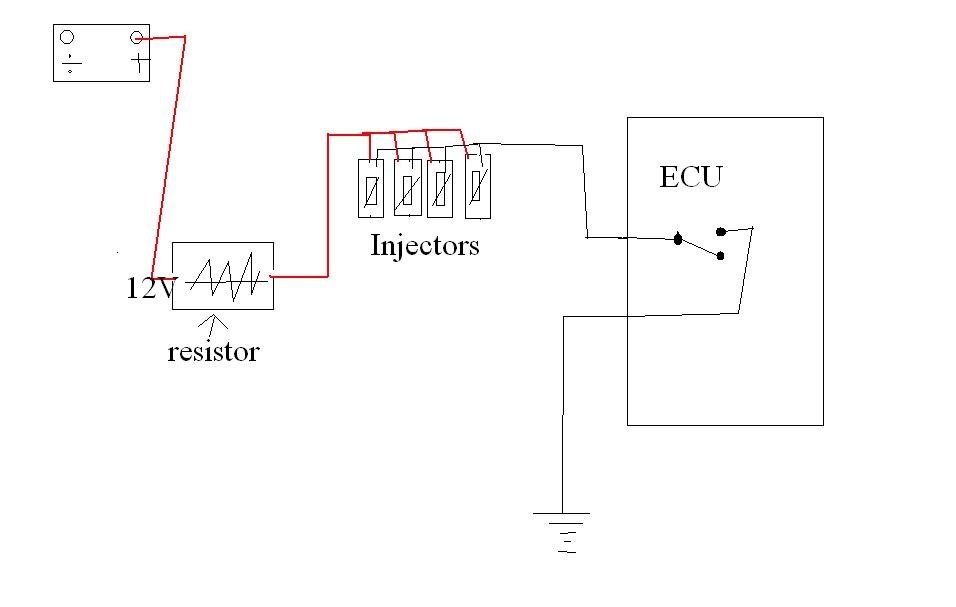
The signal injector can be applied to the speaker output and if you hear the signal you can move to the preceding stage of the circuit. If low z peak and hold or pwm controlled injectors that are lower impedance are used the wiring will require series resistors on each injector to avoid damaging the board with excessive current.

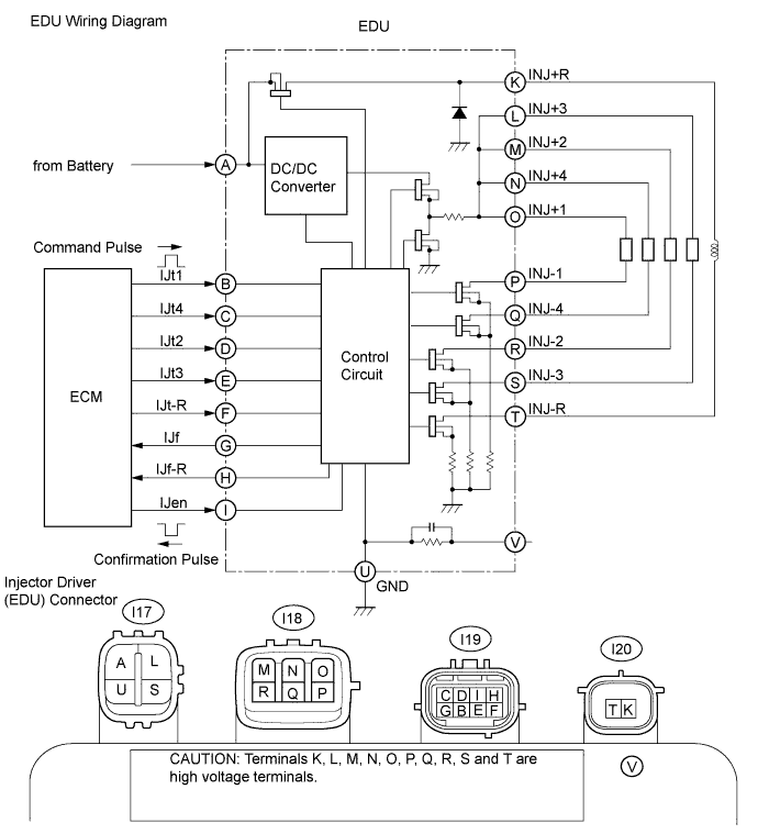
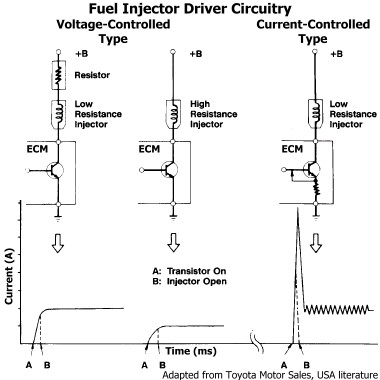
Injector Driver Circuits Toyota Engine Control Systems
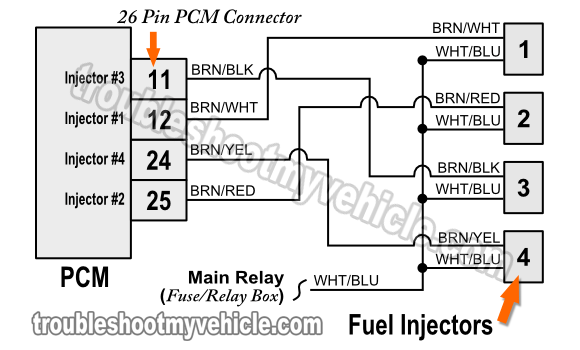
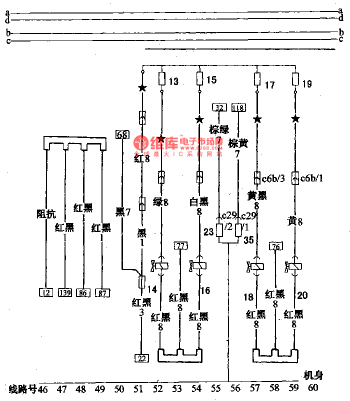
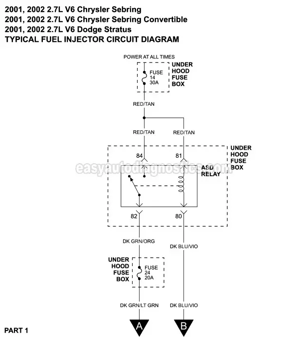
Injector circuit wiring diagram. Fuel injectors are attached to the fuel rail. Injector circuit wiring diagram duration. Speeduino contains 4 injector control circuits and is capable of supporting up to 8 injectors and cylinders with these. Using it can quickly determine the faulty stage of a radio receiver for example. A signal injector is a very useful and quick troubleshooting tool for signal tracing in a circuit. How to test for a short to ground ohmmeter vs test light duration.
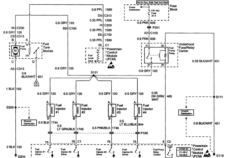
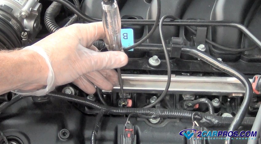
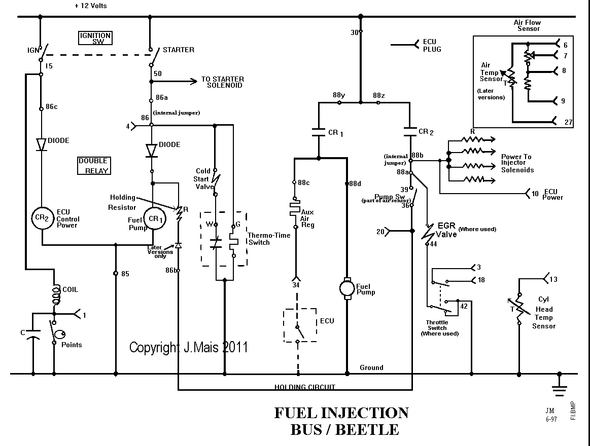
Learn to test and analyze automotive fuel injector circuits from a wiring diagram perspective. It is very time consuming to detect and prove a clogged. Wiring diagram youtube throughout fuel injector wiring diagram by admin from the thousands of pictures online in relation to fuel injector wiring diagram we all picks the best series with best image resolution exclusively for you all and now this photographs is one of photographs selections in your finest pictures gallery concerning fuel injector wiring diagram. The diagram below appears tpic46l0102 and tpic2601 circuit schematic that are well suited for fuel injector control applications.


