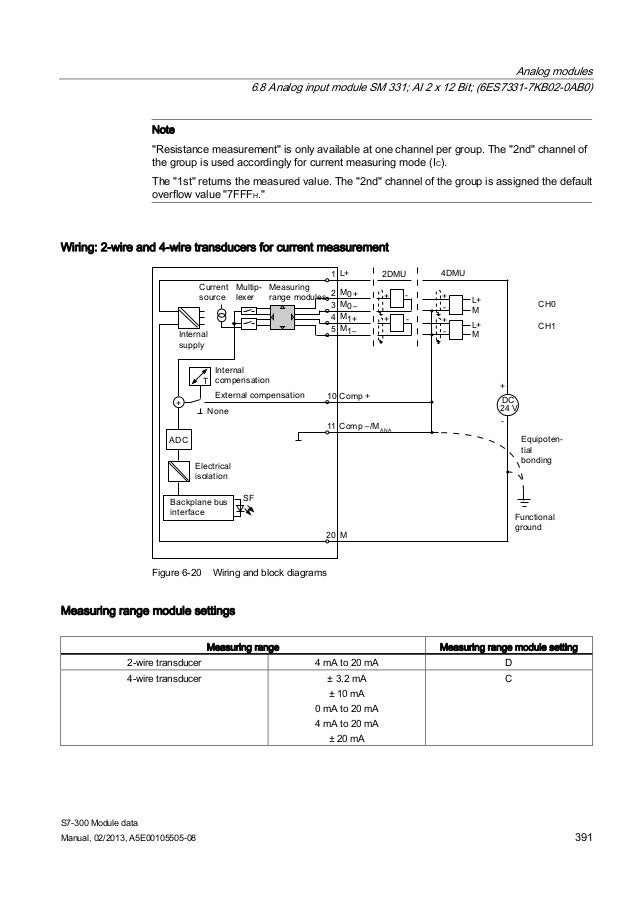
4 wire transducer to 4 wire module i am a bit confused about m m and mana. This is important to have analog deviced to have the same potential as power supply.

Current Loop Connection Divize Industrial Automation
Siemens analog input module wiring diagram. 4 wire transducer to 2 wire module 4. 0 we have started having some spiking values on 2 of our analog input channels. 2 wire transducer to 2 wire module 2. 2 wire transducer to 4 wire module 3. Analog input module ai 8xuirtdtc st 6es75317kf00 0ab0 manual 072014 a5e03484864 ac 9 properties the module has the following technical properties. Siemens provides products and solutions with industrial security functions that support the secure operation of plants systems machines and networks.
I need wiring diagram to connect 2 wire and 4 wire transducer to analog input module for the following cases. Wiring the power supply module and the cpu wiring of the analog module standard pin assignment of two measurement transducer types wiring of unused inputs configuring the simatic manager using the project wizard completing the automatically generated hardware configuration. Analog input module ai 4xui 2 wire st 6es7134 6hd01 0ba1 4 equipment manual 062020 a5e03572832 af siemens products and solutions undergo continuous development to make them more secure. I m new to control field. Analog input module ai 4xrtdtc 2 3 4 wire hf 6es7134 6jd00 0ca1 4 equipment manual 092019 a5e03573289 af. Current measurement 2 wire and 4 wire connection 2 wire and 4 wire transducer the following figure shows the block diagram and an example of the terminal assignment of the analog input module ai 4xi 2 4 wire st on the baseunit bu type a0a1.
We suspect that it is actually the input device however after reading this forum and the manual for the analog input card i would like some feedback on the existing wiring to make sure that it is correct. Analog input module ai 8xui hf 6es7531 7nf00 0ab0 manual 092016 a5e36649087 ab preface documentation guide 1 product overview 2 wiring 3 parametersaddress space 4 interruptsdiagnostics alarms 5 technical specifications 6 dimensional drawing a parameter data records b representation of analog values c. 8 analog inputs voltage measuring type can be set per channel current measuring type can be set per channel measuring type resistance adjustable for channel 0 2 4 and 6. Ok ive looked at manual and everything seems to be clear to me. Then mana and 24v of the supply must be grounded. Siemens strongly recommends that product updates are applied as soon as they are available and that the latest product versions are used.
Analog input module ai 8xi 2 4 wire ba 6es7134 6gf00 0aa1 10 manual 032015 a5e34941201 aa wiring up 3 31 wiring and block diagram this section includes the block diagram of the ai 8xi 2 4 wire ba module with the terminal assignments for 2 wire and 4 wire connection. You connect analog output with two wires ao and mana and also you should connect power supply to module.


