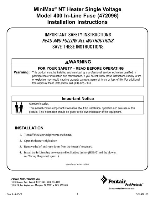
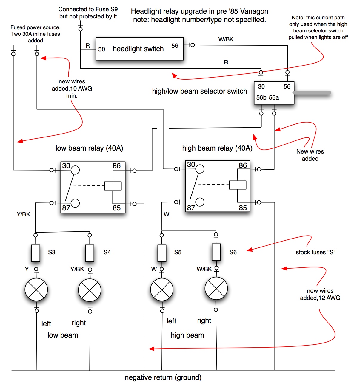
Its easy to use and compatible with windows mac and linux platforms. It shows how the electrical wires are interconnected and can also show where fixtures and components may be connected to the system.
Wiring Toyota Push Buttons For Led Tacoma World
Inline fuse wiring diagram. Main power from battery to new fuse block what size inline fuse do i needthe block says no more than125 amp but that sounds high to meyes no or please tell me the sizeits a pro team 175. Please choose a year from the menu at left to start your search. Wiring color diagram for tracker and bass tracker boats. It is very likely the invert already has a built in. Welcome to winnebago industries wiring diagrams. Battery fusebreaker to inverter.
The wiring and fusing from the battery to an acdc inverter is of critical importance because this is where the most current will likely flow. Similar to the charge controller case the recommended wire and fusing should be obtained from the inverter manual. Start with a wiring diagram software professional wiring diagram software can produce high quality wiring diagrams with less time. Use this as a reference when working on your boat wiring. 1995 chevrolet silverado 1500 57l fuse box diagram 1995 chevrolet silverado 1500 57l fuse box map fuse panel layout diagram. Crestliner manual or wiring diagram good luck.
Most manufacturers dont use them since they generally dont manufacture the instrument panels themselves. We have an in depth article here on how to wire a bilge pump check that out as well for more details. A wiring diagram is a simple visual representation of the physical connections and physical layout of an electrical system or circuit. Edraw wiring diagram software is a particularly designed application automating the creation of wiring diagrams with built in symbols. As in the diagram a wire is run from a 12 volt power source to the switch in the cab and out to the relay placing a fuse at the source of the power. Only the boat wiring from the panel backwards would you likely get any help with if they had a wiring diagram for it.
Wiring diagrams and electrical schematics f 650 chassis cab roush wiring harnesses srm c4 frpcm c6 ipts c5 flim c7 uhcan inline c3 gnd batt to splice pack pin d terminal fusebox a c4 f rpwr1 rpwr2 a c4 m roush efpr c9 ford efpr c8 uhford inline c16 uhford inline c10 uhin tank inline 1 fuel pump c11 lh tank uhin tank inline 2. Im also showing the negative return wiring for the bilge pump in this step. Notice the fuse shown this needs to be circuit protected with an inline fuse like this one. A stereo memory line might be another bypassed load. The method i use for wiring the lights and other external accessories for the most part follows the diagram pictured above.


