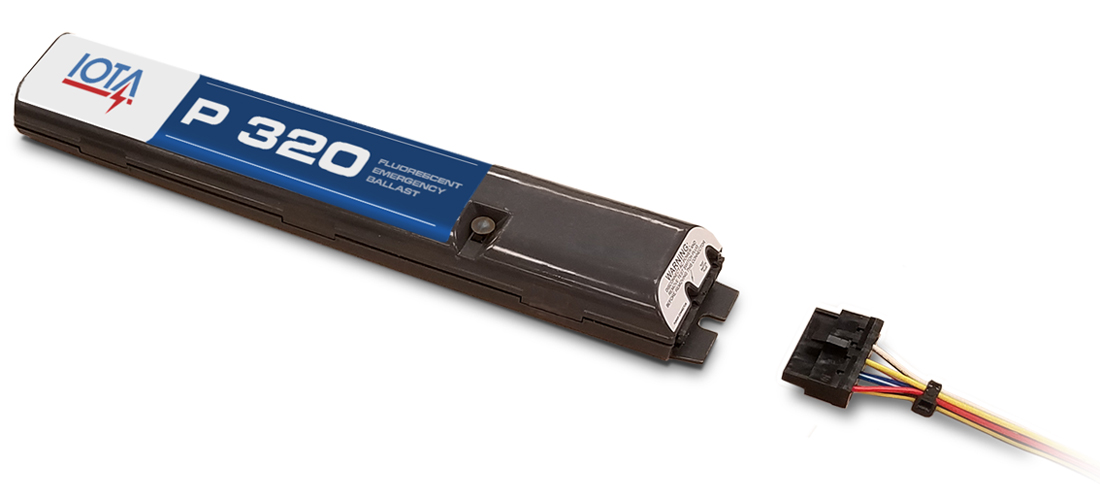
Adjoining cord paths may be shown about where particular receptacles or components have to be on an usual circuit. The i 320 series acfluorescent emergency ballast from iota engineering allows the same fixture to be used for both normal and emergency operationin the event of a power failure the i 320switches to the emergency mode and operates oneof the existing lamps for 90 minutesthe unit contains a battery charger and inverter circuit in a single can and can be mounted in the.

Emergency Solutions For Fluorescent And Led Retrofit Lamps
Iota i 320 emergency ballast wiring diagram. April 3 2019 by larry a. If a diagram cannot be found within this selection consult customer service. Iota i320 emergency ballast wiring diagram whats wiring diagram. The emergency ballast wiring guide this document has been customized to contain a wide library of individual dia grams for various installation. It reveals the parts of the circuit as streamlined forms and the power and signal connections in between the gadgets. A wiring diagram is a streamlined conventional pictorial representation of an electrical circuit.
Iota i320 emergency ballast wiring diagram architectural electrical wiring layouts reveal the approximate locations and also affiliations of receptacles lights as well as irreversible electric solutions in a building. Mount the i 320 in the ballast channel at least 2 away from the ac. Ballast emergency ballast relay how to use the emergency ballast wiring guide this document has been customized to contain a wide library of individual dia grams for various installation applications. Inputv iota i emergency ballast. When battery packs are remote mounted consult customer service for the maximum allowable distance between the battery pack and the lamp. 1remove the ballast channel cover.
The i 320 he from iota engineering is a ul listed emergency ballast that allows the same fixture to be used for both normal and emergency operation. In the event of a power failure the i 320 he switches to the emergency mode and operates one of the existing lamps for 90 minutesthe unit contains a battery charger and inverter circuit in a single can and can be mounted in the wireway or on. In the event of a power failure the i 32 switches to the emergency mode and operates one of the existing lamps for 90 minutes. The diagrams are categorized primarily according to the number of. The i 32 fluorescent emergency ballast from iota engineering allows the same fixture to be used for both normal and emergency operation. Wellborn collection of iota i320 emergency ballast wiring diagram.
A wiring diagram is a kind of schematic which uses abstract pictorial symbols to exhibit all of the interconnections of components in a very system. Iota i for 1 or 2 lamp lumen emergency ballast for 1 or 2 lamp. 2 8 single bipin t8 t12 long compact and 2 4 14w to 54w t5 ho or vho fluorescent lamps. Wiring refer to the wiring diagrams on the back page for the appropriate wiring of. Iota i320 emergency ballast wiring diagram wiring diagram is a simplified adequate pictorial representation of an electrical circuit. The i 32 can be used with most 2 4 t8 thru t12 and.
The unit contains a battery charger and inverter circuit in a single can. It shows the components of the circuit as simplified shapes and the power and signal friends amongst the devices.


