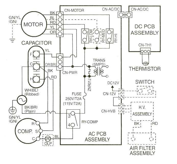
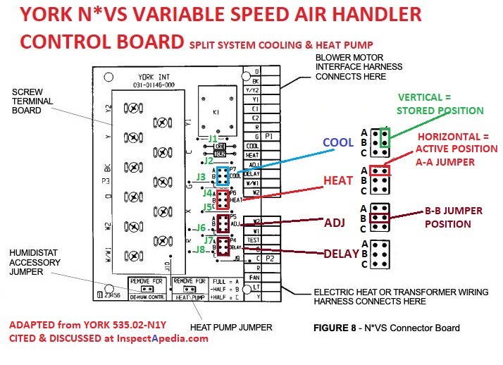
138ck018 32 34 38ckm024 32 34 38ckm030 30 32 38ckm036 and 042 33 34 38ckm048 35 36 208 230v 1 phase 60 hertz a93410 23 5 red or blk red or blk 208230 power supply 10 equip gnd l1 l2 11 21 23 blk blu blu yel yel brn blu blk yel yel h c f ofm brn blk vio blu blk blu blk yel yel lls brn y r ch. Wiring diagram index name description page aa power distribution frc 3 ab power distribution frc 4.

We 1434 Electrical Control Panel Wiring Diagram On
Ahu wiring diagram pdf. Seat suspension b f08 15a30a aux sw 1 2 brightwork b f10 10a cust. Power distribution frc 12 wiring diagram. Wiring is subject to change. Lvd2 b f28 10a cust. From this point forward ladder dia. Number 006 008 208230 3 60 460 3 60 11720011 c 1 575 3 60 012 208230 3 60 014 460 3 60 11720960 b 2.
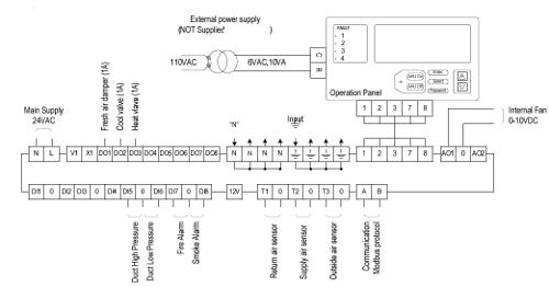
Wiring diagram manual split system air conditioner 421 03 5400 01 specifications subject to change without notice. Lvd1 b f16 20a o h socket b f51 10a i shift gecu a b f50 20a i shift tecu a b f40 5a. A wiring diagram is a streamlined standard photographic depiction of an electrical circuit. A b f71 15a center pin hot a b f60 30a hvac fan a b f61 5a lvd sens vendor ttu a b f76 30a 3968162 a f05 30a lecm4 b f06 20a rh sleeper pwr ports console b. The first and most common is the ladder diagram so called because it looks like the symbols that are used to represent the components in the system have been placed on the rungs of a ladder. Multiple power sources may be present.
Wiring diagrams index unit 50byn v ph hz label diagram fig. Wiring diagram book a1 15 b1 b2 16 18 b3 a2 b1 b3 15 supply voltage 16 18 l m h 2 levels b2 l1 f u 1 460 v f u 2 l2 l3 gnd h1 h3 h2 h4 f u 3 x1a f u 4 f u 5 x2a r power on optional x1 x2115 v 230 v h1 h3 h2 h4 optional connection electrostatically shielded transformer f u 6 off on m l1 l2 1 2 stop ol m start 3 start start fiber optic. Disconnect all power before servicing or installing this unit. Failure to do so may cause property damage personal injury or death. Assortment of rheem air handler wiring schematic. Hvac fan a b f24 20a 30a open p.
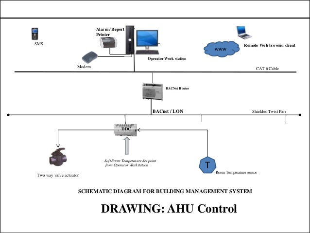
Always refer to the wiring diagram on the unit for the most up to date wiring. Aa spf44a spx03ea3 fb2a1 08 ag0 b a17b2 ai4 c frcj3c5 aq1 b mcsca9 f61a1 08 hb2 d a131ba4 f15a1 50 bi3 c x210aad f87 15a cust. It reveals the parts of the circuit as simplified shapes and the power and signal links between the devices. Types of wiring diagrams there are three basic types of wiring diagrams used in the hvacr industrytoday. 5 expanded table 340085 101 340085 101 340086 101 340086 101 340086 101 342878 101 n4a318akc100 n4a530gkc101 r4a318akc100 r4a436aka100 wca3184gkc100 n4a648gkb101.


