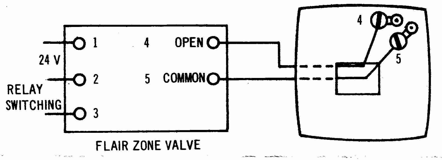
Electrical interface wiring data sheet. Numatics a leader the industry in valve technology with innovations that reduce installation wiring diagram of the numatics generation series air valves.

How To Troubleshoot An Asco Solenoid Valve Valin
Numatics valve wiring diagram. M23 12 19 pin and m27 26 pin pin outcolor code chart revised pin out color code chart for all i version m23 and m27 cable assemblies. Wiring document for all sub d m23 and m27 connector manifolds for the generation 500 series valves. M o d e l s e l e c t i o n t a b l e standard valvemounting combinations. Disconnecting piping or wiring. Numatics wiring documentation diagrams and manuals. Double solenoid valves always consume two solenoid outputs while single solenoid valves consume either one or two solenoid outputs depending on the internal circuit board single or double z board.
Table of contents l01 series technical and operating data 3 how to order 4 valve dimensions 5 manifold assembly 6 speed control kit 7. M23 and m27 connector manifolds for the generation 2000 series valves. 500 series electrical interface wiring data sheet wiring document for all sub d m23 and m27 connector manifolds for the generation 500 series valves. Override type valve function wiring option 1214 end voltage ac 2450 60 dc 100 11550 110 12060 200 23050 220 24060 12 vdc 24 vdc flush non locking override. Page 1 td500xxwd1 1en 0716 subject to change without notice. 2 z boards configured with all doubles wire to common.
Z boards configured identical to valve type wire to common example no. M23 12 19 pin and m27 26 pin pin outcolor code chart.


