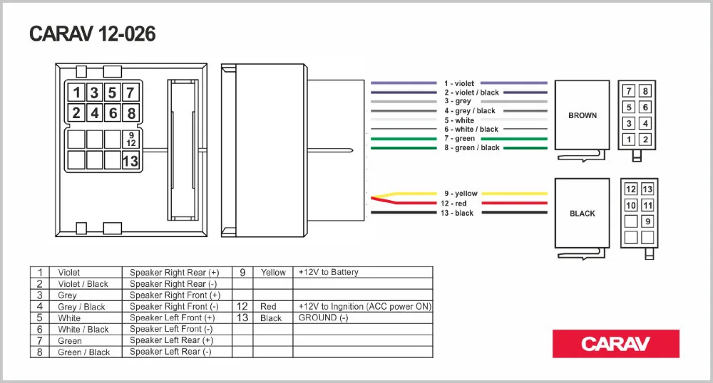
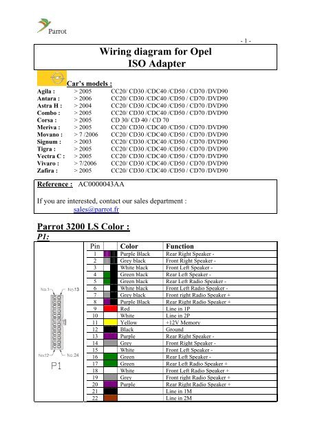
The connector wiring may vary depending on the car manufacturer. Iso wiring diagram home.

Details About Sony 16 Pin Iso Wiring Harness Loom Adaptor Wire Radio Connector Lead New
Iso wiring diagram. This connector is sometimes present on vintage vehicles and the actual wiring may be completely different from what the standard states which means that measuring before connecting is a good idea. The italian company iso began it career as a car manufacturer in the mid 50s with the release of a mini car with a transparent roof isetta as bmw produced under license by the company but in 1962 it was decided to enter the market of high quality gt car that would rivolta carried model. The 5 pin has a design and pin layout that is identical to the 7 pin iso 1724 connector with the exception for the lack of pin 1 l and pin 4 r. Like any piece of transformer operated equipment the iso boost will produce a noticeable hum when it is energized although not nearly as loud as. However only with the release of grifo a year later. The newer iso 280 relays use a smaller pin terminal that is 28mm wide and can be used in compact power distribution units and holders.
Take special care when installing into 98 or later vwaudiskodaseat models as there may be a 12 v connection on pin a5 which could damage the car stereo or into ford from 97 or later with an iso connector on which damage to the cars microcomputers is possible if. Iso relays are designed for use in the automotive industry and adhere to a standard pattern for their electrical terminals. Joined may 12 2009 6. Electrical diagram method 2 see figure 5 for wiring connections choosing mounting location after selecting a wiring method the mounting location must be chosen. Start date may 18 2009. Iso car manual pdf above the page rivolta.
May 18 2009 1 i need to know how to wire up a 5 hp 220 single phase with 2 run and 2 start tubes.


