Do not connect this wire to any factory ground points. All the contacts in the receiver are dry relay contacts.

Children Electric Car 2 4g Bluetooth Remote Control Toy Car
Jr rx 12v wiring diagram. 3 green d2d rx 4 red 12v bitwriterdirected smartstart harness black 3 pin connector 1 red 12v 2 orange esp 2 rxtx 3 black 12v wire descriptions main harness white 5 pin connector black. A red led will indicate that the bcm is powered and receiving 12 vdc. F24 receiver mounting diagram 2. Wiring guide for the bcm to dc gnd rx tx page 4. Dc gnd rx tx and 12v are on the back of the dc. 12v power cntrl ksi amp 7 6 14 blue 18awg foward forward reverse switch note 1 main c on ta r note 3 a 1 a 2 r4 deuts ch dtm 0 6s w v u u v w b r 3 5 p i n b c o n n e c t o r s e e r 1 motor yellow black 18 awg rx seri al display 1 5 6 8 s1 pot high black white 18 awg blue 18awg blue 18awg notes.
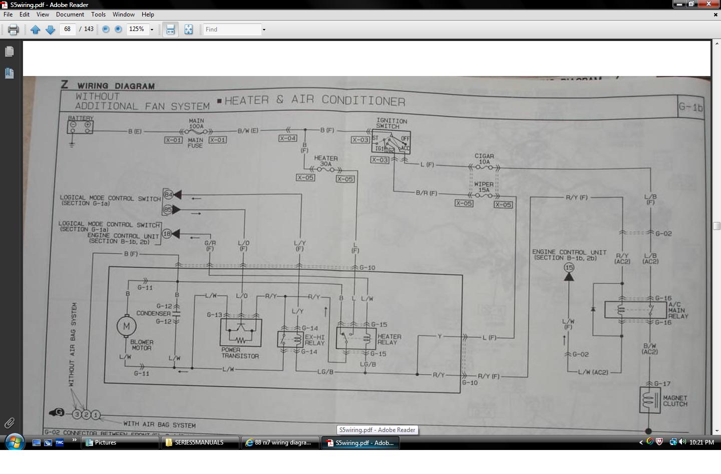
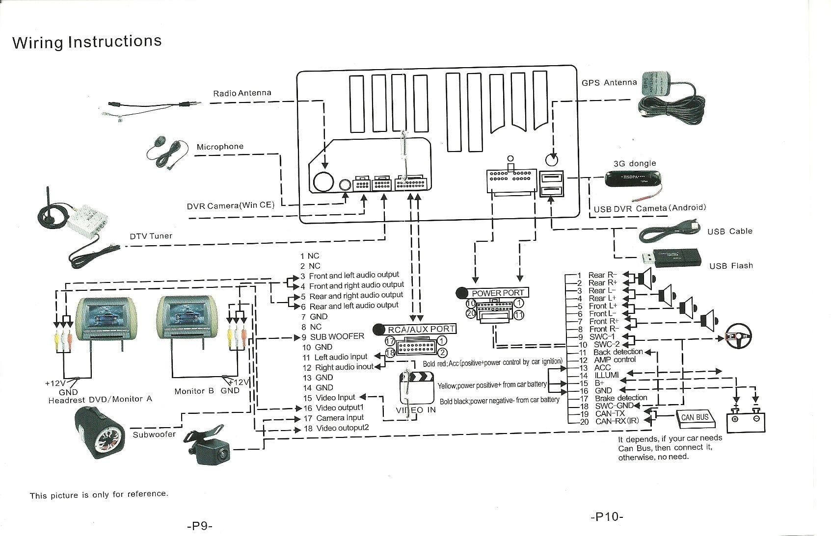
Wiring diagram connections goodman heat pump thermostat wiring img source. Types of rv electricity there are 2 main types of sources of rv electricity within your rv 12 volt dc and 120 volt ac same as 110 volt just like your stick brick for our purposes. 26 rx ncv j13hdmi19rearj13hdmi19rear. Circuit diagrams for rx23l kenwood in pdf format. Chassis ground this wire is the units source of ground. Lexus owners manual wiring diagrams 1990 2018 lexus is a division of toyota which produces luxury models for the us and european markets naturally with the left rudder.
The wires are identified on the label on the top of the receiver and on the wiring diagrams on page 15 of this manual. The very word lexus in its sound is similar to the word lux. The rx pin on the dc connects to the tx pin on the bcm. The bcm should be wired correctly without loose connections and 12 vdc connected at pin 35. Below is a rv electric wiring diagram or schematic including the converter and inverter for a generic rv. The tx pin on the dc connects to the rx pin on the bcm.
Ground receive transmit and 12 vdc power in gnd rx tx. This means that is there is no internal. 3 wiring connection diagram. 1 if reverse is not. 12v pow rcnt l ksi s6 amp 7 6 14 foward blue 18awg forward reverse switch main c on ta r note 3 a 1 a 2 r2 deutsch dtm 06 6s w v u u v w b 3 5 p i n c o n n e c t o r s e e r 1 motor black blue 22 awg redwhite 22 awg t an 2 wg tan b lack 22 awg blac k 22 awg pur le 2 awg yellow black 18 awg rx se ial display 1 5 6 8 s1 blue. The f21 receiver wires are color coded and the f24 receiver wires are numbered.
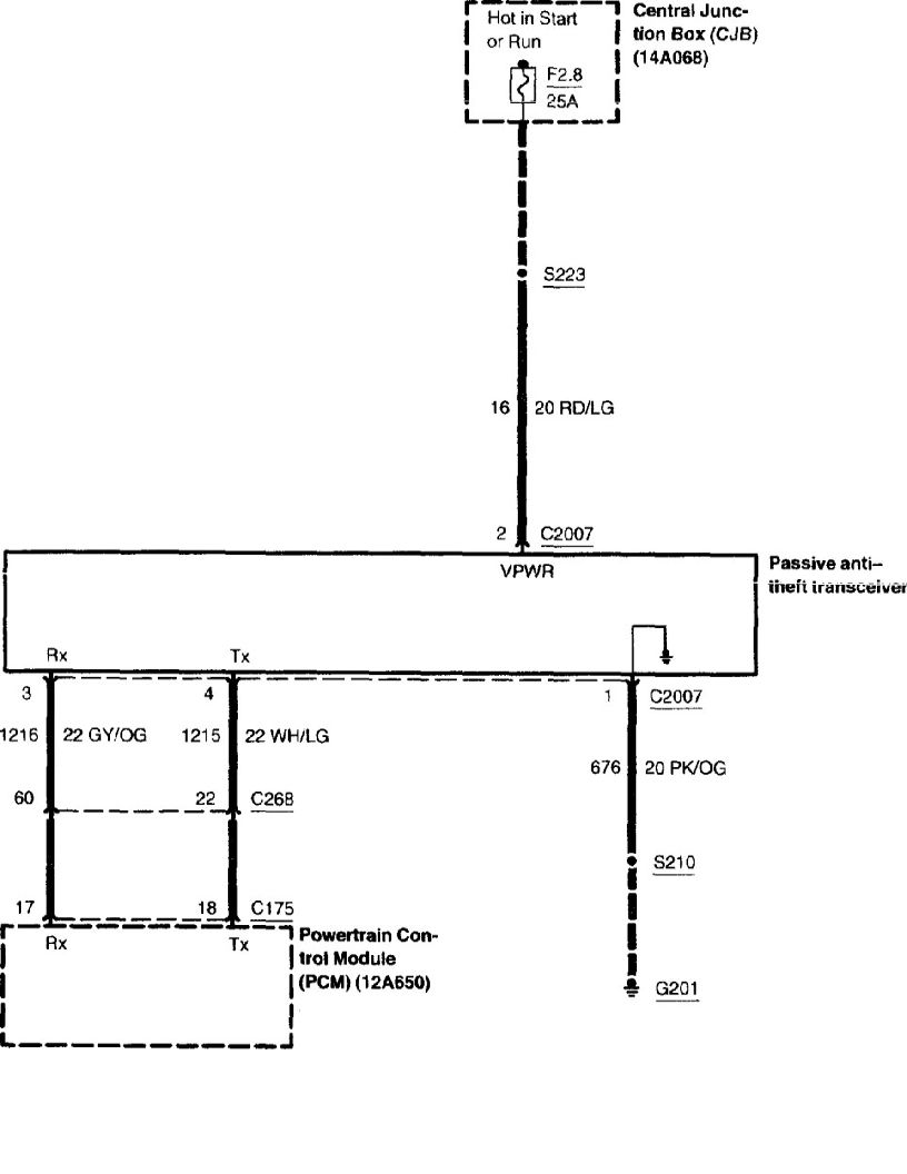
Lvds wire connection wire12v input for power board connection wirefor keyboard and remote 38. If the tx and rx wires are crossed the dc and bcm will not communicate and no functions will work. The dc is connected to the bcm with 4 wires in the upper right corner of the board.
Gallery of Jr Rx 12v Wiring Diagram


