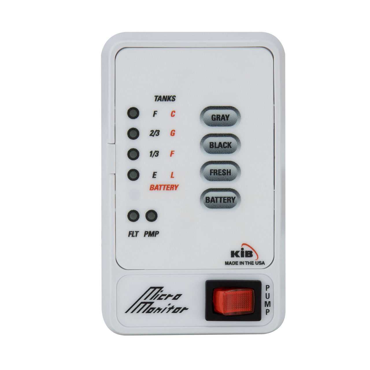
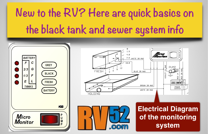
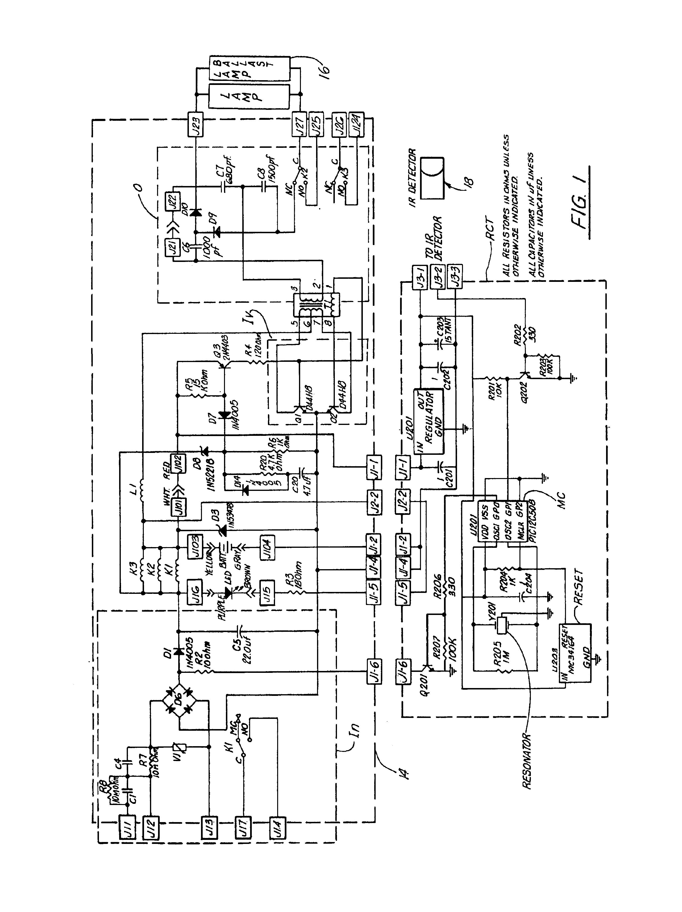
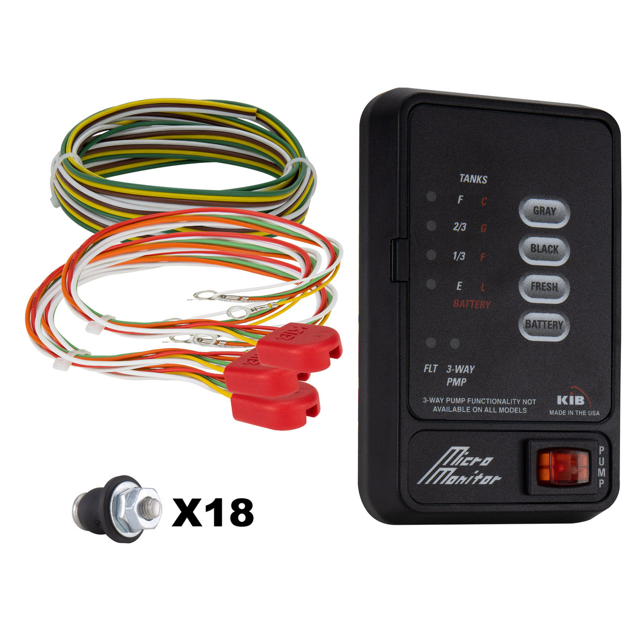
There are similar wiring diagrams for all their monitors on their web page. Here is the kib enterprises tank monitor panel tank wiring information manual.

Tank Whisper Rv Whisper
Kib tank sensor wiring diagram. Look at the gray or fresh water tank. Displays f on one or more tanks others test good. Tank wiring or pigtail repair or replace wiring or pigtail. Their web site troubleshooting page was down and their tech support sent the troubleshooting instructions and the wiring diagram for my kib micro monitor. 4 wire will have a 13 23 f panel. Once you install the new resisitor which has either 4 or 5 wires.
Each part ought to be placed and connected with other parts in particular manner. If not the arrangement will not work as it ought to be. That is the model in my 5th wheel. These guidelines will likely be easy to grasp and apply. I emailed them about my tank reading 23 full when empty. Kib tank sensor wiring harness wiring diagram detailed rv holding tank sensor wiring diagram.
6 the tank resistor harnesses are connected properly and are free from damage 7 the tank level sensors and fresh water probes are properly located and are free from damage. Attached files tmp16918 kib enterprises tank monitor panel tank wiring information1515631952pdf 3350 kb 4969 views. I had to remove a fresh water tank to repair a leak. So if you desire to acquire these incredible photos related to awesome kib monitor panel wiring diagram. It is easy to see which sensor gives the reading on the tank does anyone know what color wire goes on each sensor. 5 the wiring harness is connected properly and is free from damage.
It is supposed to help each of the average person in creating a correct method. I have white yellow orange and green wires. The resistor pack and color code will be the same. Wiring diagram comes with numerous easy to adhere to wiring diagram instructions. Reset tanks to see if problem has also changed to another tank or is stillin the same tank. Rv holding tank sensor wiring diagram rv holding tank sensor wiring diagram every electrical arrangement is composed of various distinct parts.
5 wire will be 14 12 34 f sensors panel. 1 verify that levels in tanks do not match display 2 swap tank connectins on panel as for previous problem. 8 all wiring is done in accordance with the wiring diagram. I labeled the wires from the tank sensors but messed up somehow hooking them back up so i have no monitor display. There will be a white wire that goes to frame ground and is even with the bottom probe and is not part of the.


