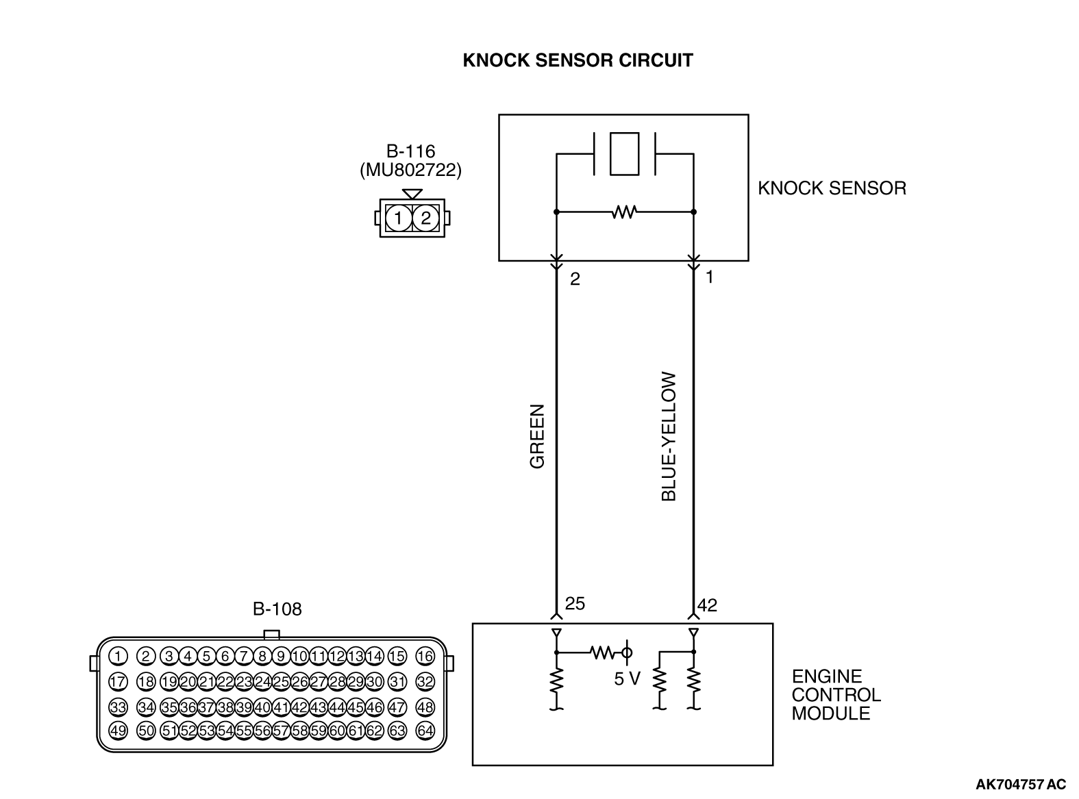
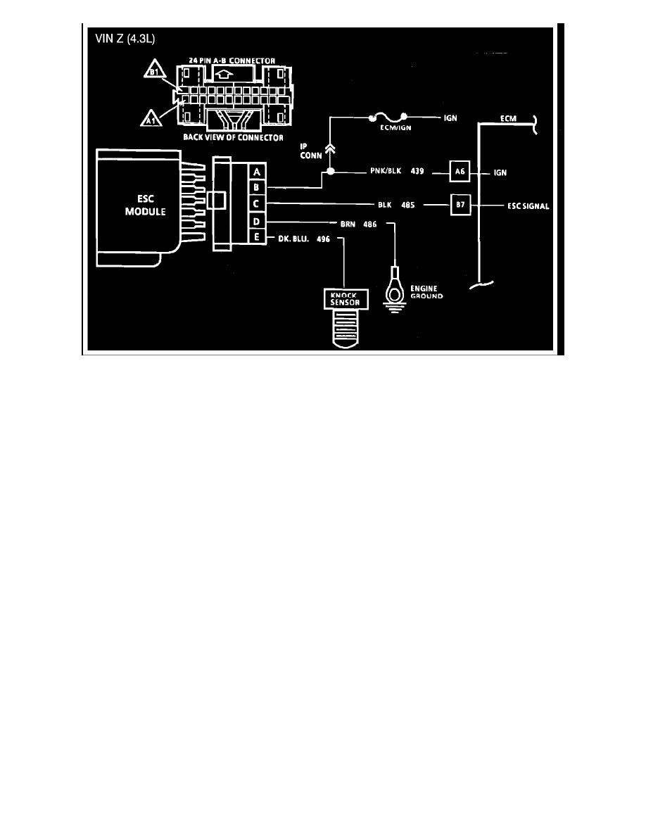
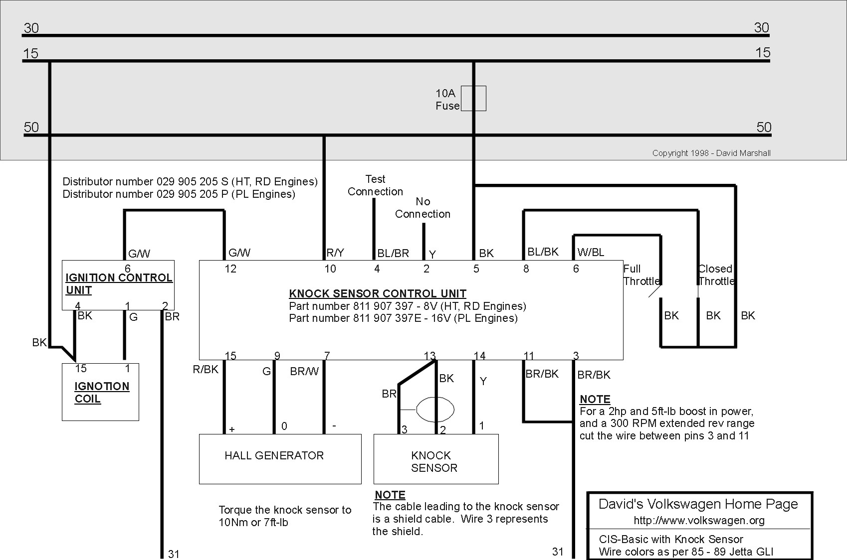
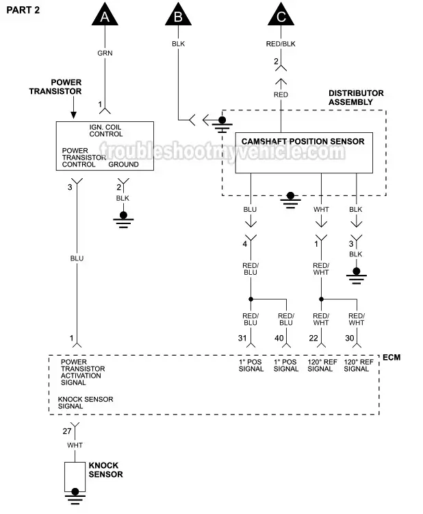
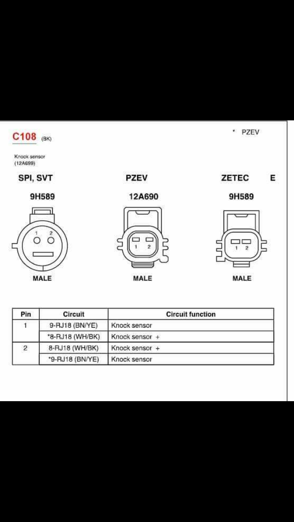
1 knock sensor 2 12a 2 female documents similar to ford wiring diagrams. The check engine light and knock sensor related obd codes will immediately point a technician to the knock sensor.
Honda Knock Sensor Wiring Diagram 03 Honda Pilot Have
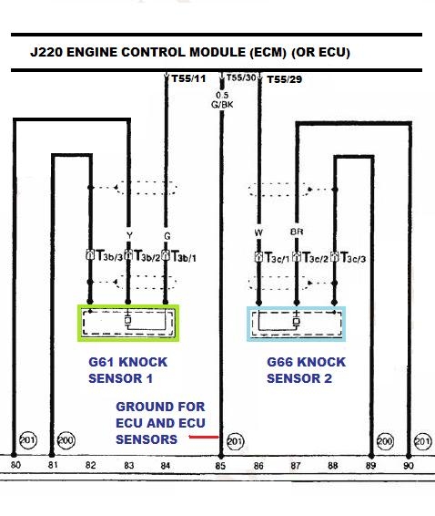
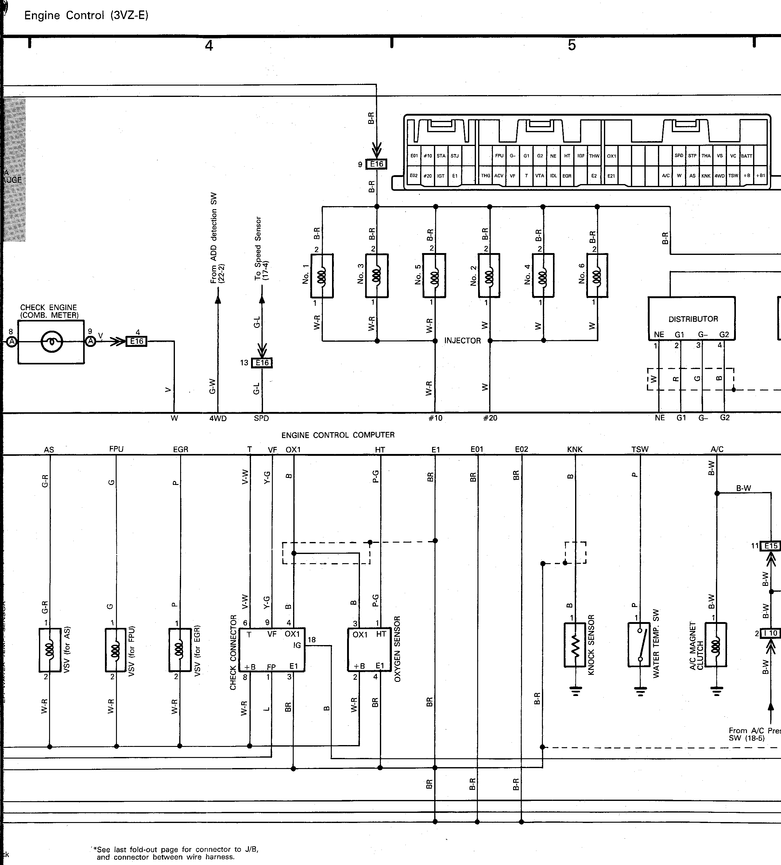
Knock sensor wiring diagram. I need a knock sensor wiring diagram because i have a knock code changed the sensor torqued and still have the code. The tan wire ecm ground is connected to the o2 sensor low wire for the 1227727730 speed density engines. This is ecm terminal e15. 1 and 2 are the knock sensors in diagram below. This section will contain general information on how to troubleshoot wiring harness and repair connector procedures. If drive around with the check engine light on when a code p0332 or a p0327 is set in the computer memory engine damage could occur.
I untaped the wires and i found a cutted black wire. The two knock sensors are bolted into the cylinder block under the intake manifold. The two sensors share a common wiring harness using one electrical connector. The reason for this is the sensor generates its own voltage and is case grounded. Anyone have a schematic for the years in question. Knock sensor location diagram.
The ecm sensor purple input goes to the appropriate input to the ecm. Im trying to see if a 2wire knock sensor can be wired in somehow to a 99 1 wire harness. To me the most interesting part about the knock sensor is that it only has one wire going to it. What is the wiring differences between the 99 01 1wire knock sensor and the 2wire 02 07. Feb 27 2017 jeep cars trucks. It aint a swap or.
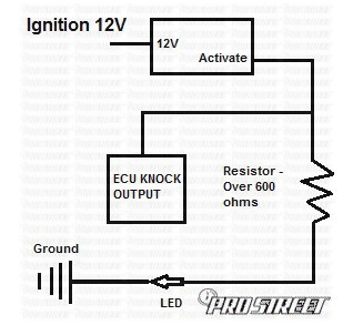
The diagram above shows how simple the installation is. Theres 3 wires going to the knock sensor 3 wires total but it is a 2 pin connector so i dont have a clue of what the black cutted wire is doing there. On the1226870 1227165 maf ecm it is ecm terminal d6. Because of this they must be replaced as a pair.
