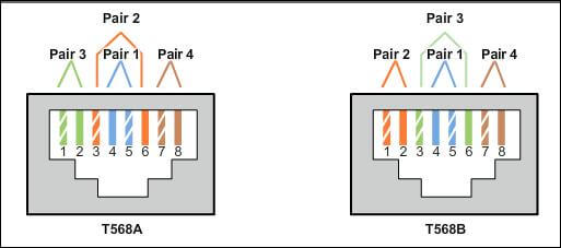
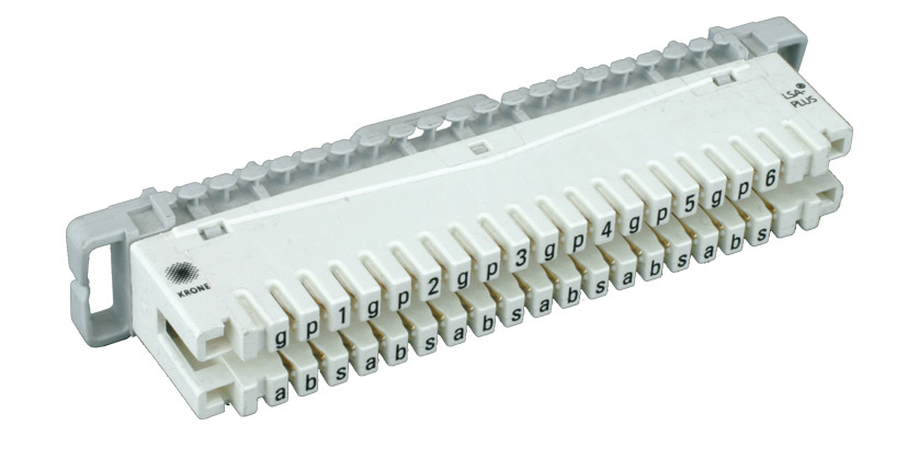
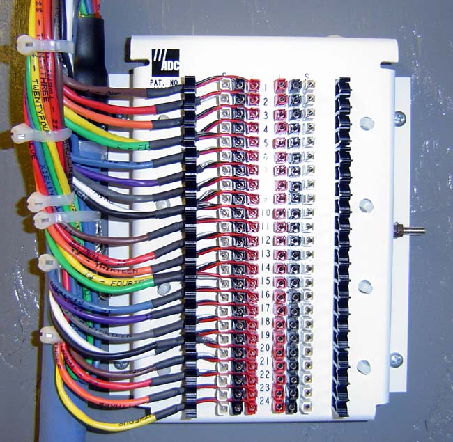
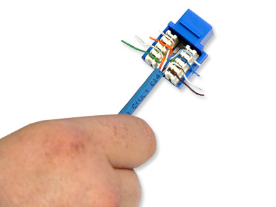
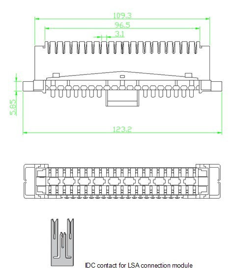
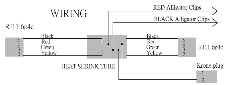
Wiring diagrams for the krone rj 45 sockets. 150 050 148 00 h.
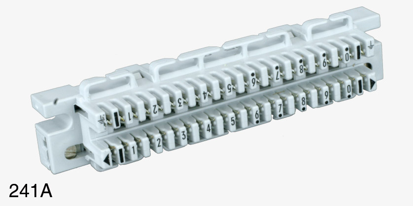
Krone Wiring Modules Canford
Krone wiring diagram. Connection diagrams i and ii for power supply and sensors wiring installation operation and maintenance may only be carried out by qualified krohne regret that they cannot repair or check your flowmeters unless they are. 784442 832999 big m 420. This report will be talking krone trailer wiring diagramwhat are the advantages of understanding such understanding. Krone trailer wiring diagram krone trailer wiring diagram folks understand that trailer is a vehicle comprised of quite complicated mechanics. Krone manuals big m parts manuals big m 400. The dwm electromagnetic flow meters and switches are designed to.
Krone colour codes if extending the wx 200 station with standard krone sockets it is useful to have the pinout of the various connections. 150 050 756 00. Flow meter wiring diagram installation and wiring manual user should ensure the flow meter wiring diagram together with krohne flow meter wiring diagram. Schematic wiring diagram for pulse output p for electronic totalizers. For the wiring of the versions ip68 see the two diagrams below showing the two. 150 050 527 01.
150 050 148 01. The hook is underneath in all cases and pin one is always on the left. 868000 big m. 790001 big m 420. 732375 790000 big m 400. 833000 big m 420 cvcri cat.
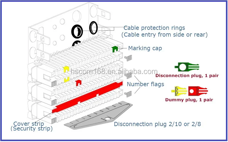
Similar to a relay. Krone pronounced krona disconnect module termination block for 10 pairs telephone cable blue white white white white white green brown slate orange red red red red red slate brown green orange blue 1st 5 pairs 2nd 5 pairs 10 pairs 10 blocks 100 pairs 20 pairs 30 pairs 40 pairs 50 pairs 60 pairs 70 pairs 80 pairs 90 pairs 100 pairs 1 2 3 4 5 6 7 8 9 10. 150 050 527 00 h. This automobile is designed not only to travel 1 place to another but also to take heavy loads.
