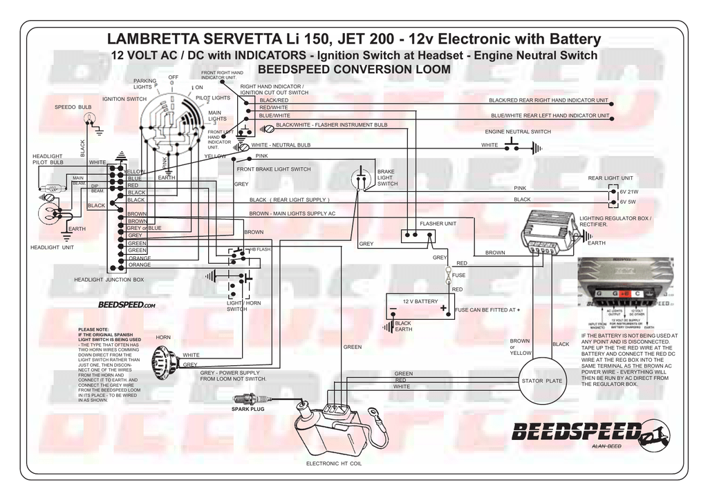
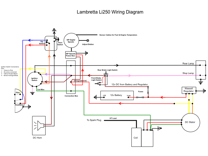
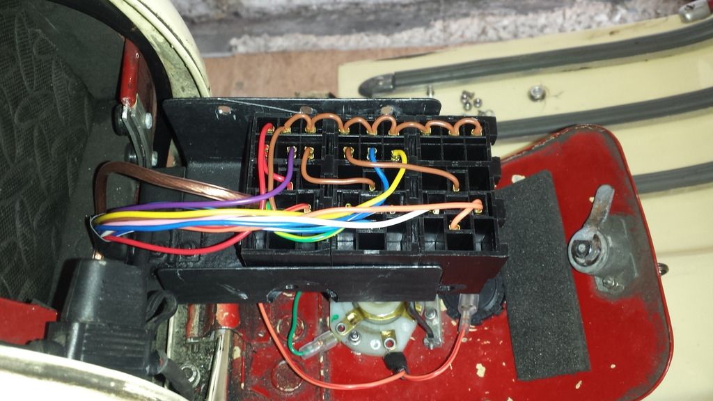
I did a little bit of experimenting tonight to check the wiring for the speedo using a 12vdc power supply wired direct to the speedo system. In most cases now you can pretty much follow the lambretta family of colour coding for wiring.

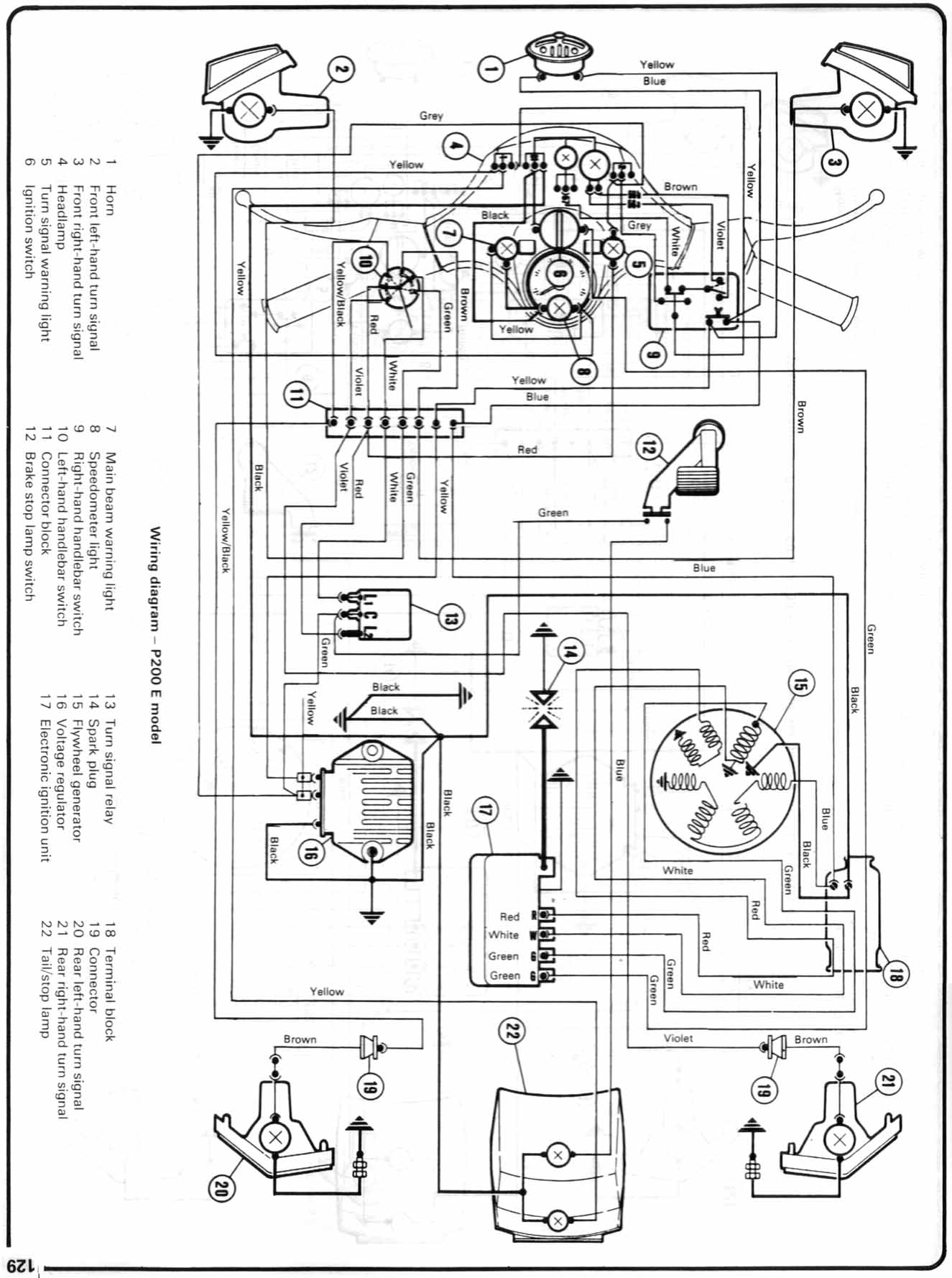
P200 Wiring Diagram Modern Vespa P Another Headlight Wiring
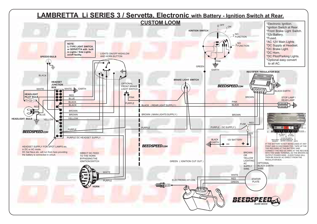
Lambretta sip speedo wiring diagram. Heres the thread with the scootrs switch diagram for your info. I presumed it wrote the settings to memory on a small chip i maybe wrong. The regulator will need mounting somewhere the most convenient point being on a bracket on the opposite side to the coil on the rear frame or to the rear. By tractorman wed feb 25 2015 850 am. This is a factory or a point of assembly issue. The modified wiring diagram below is for the series 3 li non battery model other models being wired to the regulator in a similar way.
If you break the wiring down into sections it becomes easier still. I can do it but with lights on as well. The wiring under speedometer controlling speedometer signal lights head light gage illumination re gen and battery charge indicator. By eden sun feb 08 2015 141 am. We explain the functions with reference to. Board index lambretta help.
Wiring diagram for px200e. 140 kmhmph 140000 rpm. It can measure your speed with the conventional speedometer cable and drive assembly or alternatively with the electronic wheel revolution sensor kit separate. With more and more machines becoming non standard in terms of parts fitted and used the old wiring diagrams mean less in terms of how your scooter needs to be wired. For a battery model use a px battery model regulator. Re the sip speedo its the rev counter feed that has caused problems for users in the past as it needs an ac pulse.
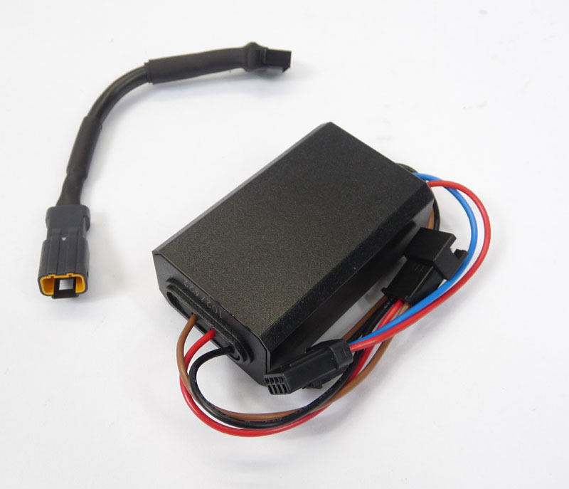
In this video we explain to you how to connect and wire the new sip speedo tachometer rev counter 20 for different vespa models since june 2014. Rev counterspeedometer sip v20 for lambretta li 125150 s12 tv 175 1. Im going to take the red wire from the speedo power box to the terminal marked c second from the left on the regulator 17the brown wire im taking to the terminal marked g second from the rightthe black wire i will ground to the regulator with the existing grounding wiresthe speedo power box will. Looking for a way to wire up an ignition switch controlled live on scooter with dc electrics bgm stator for a sip speedo. The wires for these coming out from under the indicator assembly to the male connector and the female connector have been stressed worn to breaking point. The mb diagram is fine for a standard 12v dc wassel conversion but you are using one of anthony tams dc ignitions so the wiring will be slightly different hopefully ant will have supplied a wiring diagram with it.


