Model sp replacement 4 way wiring harness. Rv steps replacement parts accessories lippert components.
30 Rv Electric Step Wiring Diagram Wiring Diagram List
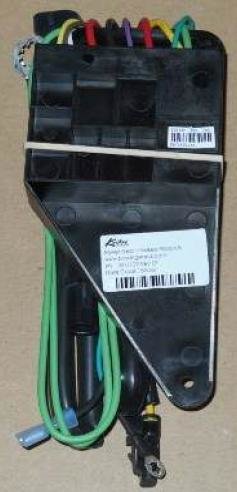
Lci step control module wiring diagram. Today were going to be taking a look at the replacement control module for an electric coach step. It attaches underneath the steps base with 4 screws not included. Replacement control module for lippert electric coach step rv step replacement step module recommendation for scs frigette coach step jan 12 entry step problems. Kwikee step light wiring diagram. Locked rotor state test for power gear step control boxes. This write up covers scsfrigette and kwikeecoach brand steps.
The replacement control module for lippert electric coach step lc301702 has the purple wire that connects to the door light switch. This replacement control module is the brain that enables your single double or triple electric lippert coach step or stromberg carlson sliding step to function properly. Step 2 called for in wiring diagram and the step control unit and the vehicles. If you do so choose. Kwikee didnt figure this out. This replaces the control module that came standard on your single double or triple electric.
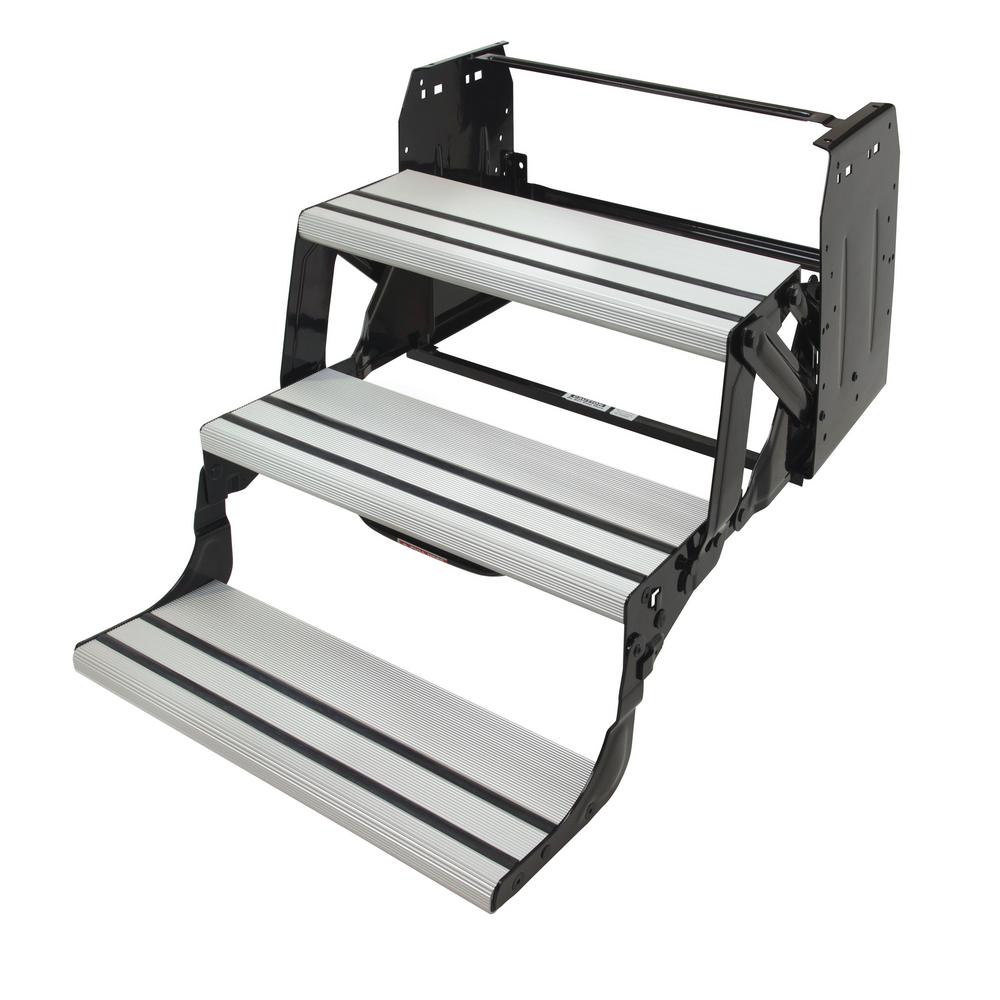
Step 1 wrap electrical tape around the black plastic loom of the wiring harness every. Kwikee step identification and replacement parts guide 82 st0501. Or just unplug the step control module lippert made these modules generic to all their steps bravo. Here you can find a document containing all of the owners for all our product lines. Replacement lippert coach step control module and motor for 2001 holiday rambler wiring diagram for installing lippert power steps module lc301702 how to wire the replacement control module for lippert electric coach steps lc301702. We have everything you need when it comes to rv steps from the lippert solid step to kwikee steps power manual options single thru quad assemblies more.
The other end of the switch lc301694 connects to the replacement wiring harness for lippert electric coach step lc301692ive attached a wiring diagram to assist. Installation van step bracket mounting ford. Wiring diagram for step with control unit vehicle wiring motor assembly understep light not available on all step models 12 awg green ground to step top control unit black four way connector 16 awg brown 16 awg yellow 12 awg red 16 awg white step switch chassis ground normally open magnetic door switch 20 25 amp fuse or curcuit breaker. 9510 control unit operation guide. The control module is what shuts down when the steps strike an object. Installation van step bracket mounting chevygmc.
Lippert components brand step motor.


