Load resistors should be your very last resort if you cant find a replacement led flasher that will work with your vehicle. Led light emitting diode lights are low current electronic components.

Tw 8270 Led Turn Signal Wiring Diagram Schematic Wiring
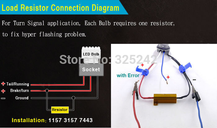
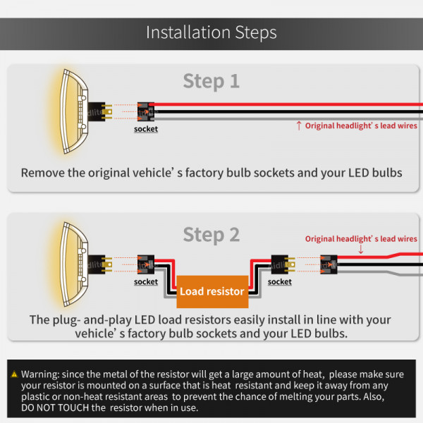
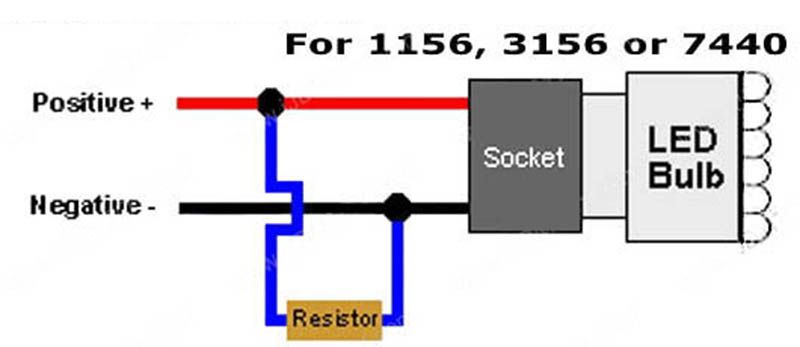
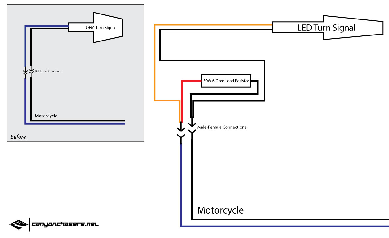
Led load resistor wiring diagram. Each part ought to be placed and linked to other parts in specific way. Using the enclosed quick connects connect one end of the resistor to the power wire and the other end of the resistor to the ground wire. As such they cannot be connected directly to a typical household battery without running the risk of burning out from too much current. Otherwise the structure will not. A replacement flasher has the added benefit of being plug and play requiring no modification whatsoever to your vehicle or its wiring. When taking it to ac 230v.
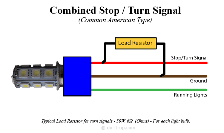
There is no concern about which end of the resistor is connected to power and which to ground. Dont use a 50 watt resistor just because some guy on the internet tells you to. Led turn signal load resistor wiring diagram stopturn signal a typical load resistor for a 21 watt turn signal light bulb would have a rating of 50 watts 6 ohms. Slip the quick connect onto the vehicle. Though please check with your supplier. To prevent a single led or chain of leds from burning out a resistor load is placed in the circuit to.
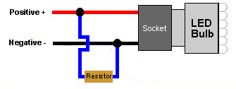
Led load resistor wiring diagram load resistor instructions plasmaglow led productsled bulb bulb socket splice here splice here ground wire power wire load resistor using the diagram below splice the load resistors wires in so that it connects across the positive and negative wires of. Led load resistor wiring diagram led autolamps load resistor wiring diagram led load resistor wiring diagram every electric arrangement is composed of various distinct components. See diagram the resistor can be installed in either direction. Calculating the size of a load resistor.
