When maximum service life is a must when an actuator offering unsurpassed strength and durability is required choose a three decade veteran of the nuclear power industry. Limitorque actuation systems 7 smb disassembly and reassembly 7 1 71 smb 000 7 1 711 smb 000 disassembly 7 1 712 smb 000 reassembly 7 2.

Wrg 1641 Limitorque Mx Wiring Diagram 20
Limitorque smb wiring diagram. Refer to figures 2 11 and 212. Electric power train. 1401054 0615 2 contents 1 introduction 6 11 purpose 6. Limitorque smb wiring diagram wiring diagram is a simplified okay pictorial representation of an electrical circuit. The limitorque smb 000 is the smallest version of the line but its operation is closely matched by the smb 00. Limitorque l wiring diagram diagrams engine smb limit switch smc mx manual b actuators mx qx l drawings parts list programming setup mx suppliers quarter turn gearbox dimensions io image source.
Flowserve limitorque smb multi turn actuators. Limitorque actuation systems standard control features 3 protection features 4 optional control features 5 ddc foundation fieldbus profibus control system 6 the wiring diagram for all standard mx actuators is shown on page 9. Check all unit wiring to ensure that it coincides with the applicable wiring diagram. Extraordinarily solid construction gives these actua. Limitorque smb seriessb series fcd lmenim1401 05 a4 615. Figure 2 10 is an exploded view of the smb 000 actuator.
Carefully check for correct motor rotation direction. A cookie is a small text file that is placed on your computers hard drive by your web browser when you visit a website. Limitorque wiring diagram gallery. Noah actuator wiring diagram dolgular of auma valve actuator wiring diagram image source. Figure 411 typical wiring diagram built in reversing starter and control station for a three phase power supply 31 figure 71 smb 000 parts diagram side view 42. If the motor is driving the valve in the wrong direction interchange any two leads on three phase motors.
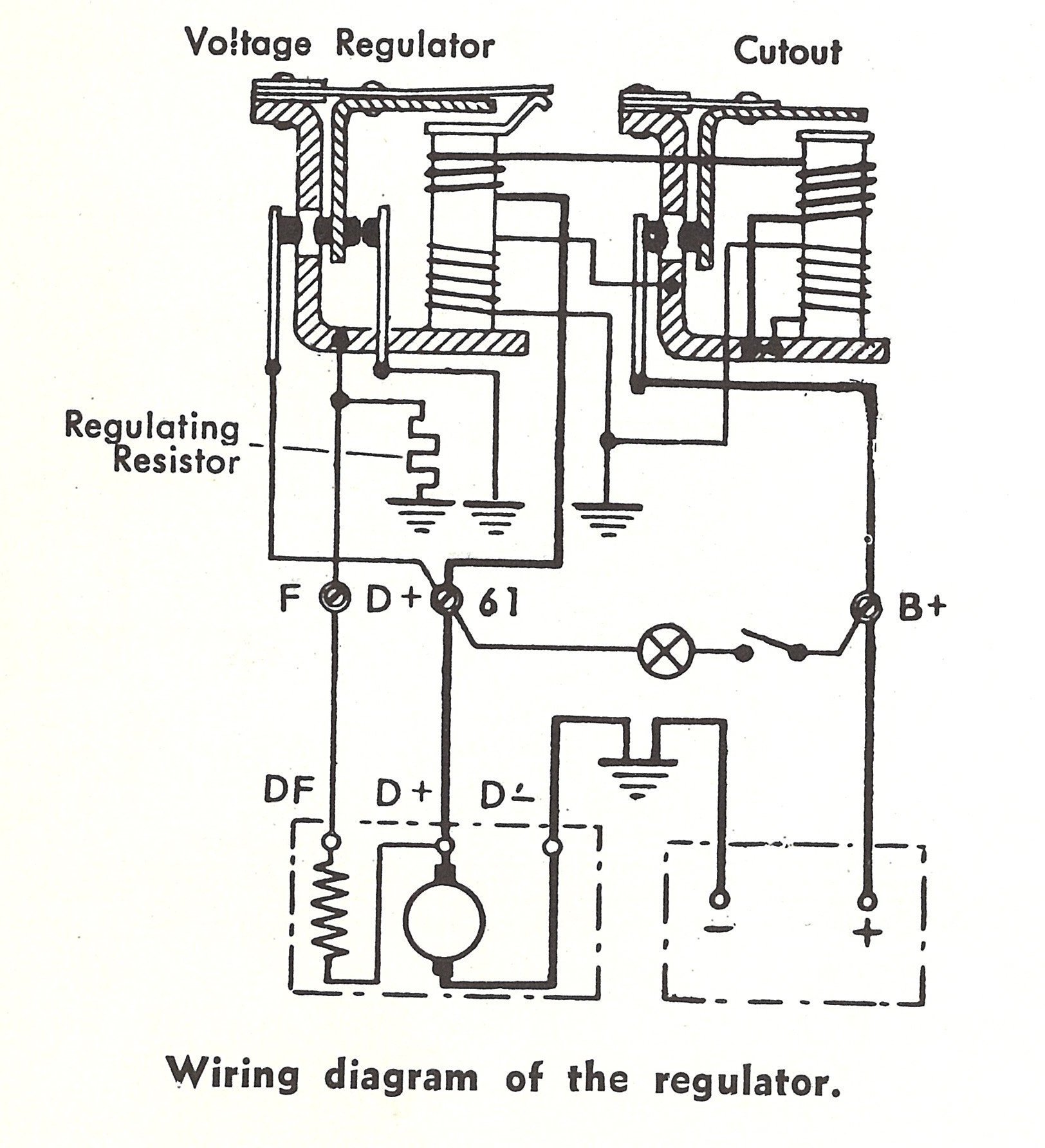
The flowserve limitorque smb series. Figure 410 typical wiring diagrambuilt in reversing starter and control station for a three phase power supply 4 18 figure 71 smb 000 parts diagram side view 7 4. In the electric mode operation begins with rotation. A wiring diagram is a schematic which uses abstract pictorial symbols to show every one of the interconnections of components in the system. Cookies enable websites to access information about the pages you visit and your actions and preferences such as login language font size and other display preferences over a period of time. It shows the components of the circuit as simplified shapes and the facility and signal friends amid the devices.
Mxa wiring diagrams single phase.


