Seal and body lb7 lly lbz lmm lml l5p duramaxtransmission leaking by wire harness. Please click the blue links.

Yamaha Yfz 450 Wiring Diagram Diagram Yamaha Wire
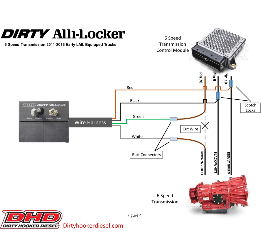
Lml duramax wiring diagram. When can traffic is detected by the switch ie when the ignition is turned on the switch. Simply get the engine and transmission in place plug our wiring in and hit the key its that simple. Duramax alternate fire camshaft street. Jun 11 2014 duramax engine diagrams. Figure 1 figure 2 figure 3 figure 4 egr inspection before starting the egr cleaning service inspect the egr components for severe deposits or clogging. 1 5 6 3.
See more ideas about duramax diagram duramax diesel. Lbz 2006 2007. Lml alternate cam firing order wiring instructions factory firing order. The truck is a lmm. Swap specialties builds a brand new setup that will allow your lb7 lbz or newer 66l duramax to be standalone and operate with a 3 wire hookup turn key. I got something weirdwiring wiring diagram.
Gm duramax 66l 20112016 lml continued continued. Lb7 2001 2004. Gm l duramax allison transmission internal transmission wiring harness by allison part number duramax truck lly vin code 2 seal and body lb7 lly lbz lmm lml l5p duramaxtransmission leaking by wire harnesslbz duramax wiring harness diagram custom wiring diagram lmm duramax engine diagram example electrical wiring diagram u rh. We can also provide you with customizations that better fit your projects needs. H is 2001 2005 lb7lly duramax 1 is 2006 2010 lbzlmm duramax 2 is 2011 2016 lml duramax and ford superduty 11 17 switch wake upsleep source this programming mode is to setup the switch for automatic onoff based on can bus activity. Af wiring instructions below.
Lgh and lml diesel engines module 1. 1 2 7 8 4 5 6 3 alternate cam firing order. Could some one tell me where to find a schematic or diagram for the engine starting circuit. Manual cleaning may be required by scraping sucking wiping etc before performing the service. We have determined plenty of references about duramax engine wiring harness diagram but we believe. Fuel return system diagnosis 1 4 engine cranks but does not run continued constant pressure regulator on lgh and lml engines the high voltage piezo injectors require that the return side of the fuel system is pressurized for proper operation.
Lly 20045 2005.


