Before making any adjustments or taking the shifter out of park be sure that the vehicles tires are blocked and the. Curved aluminum brake clutch pedal pad cover installation instructions.

Diagram Based Simplicity Safety Switch Wiring Diagram
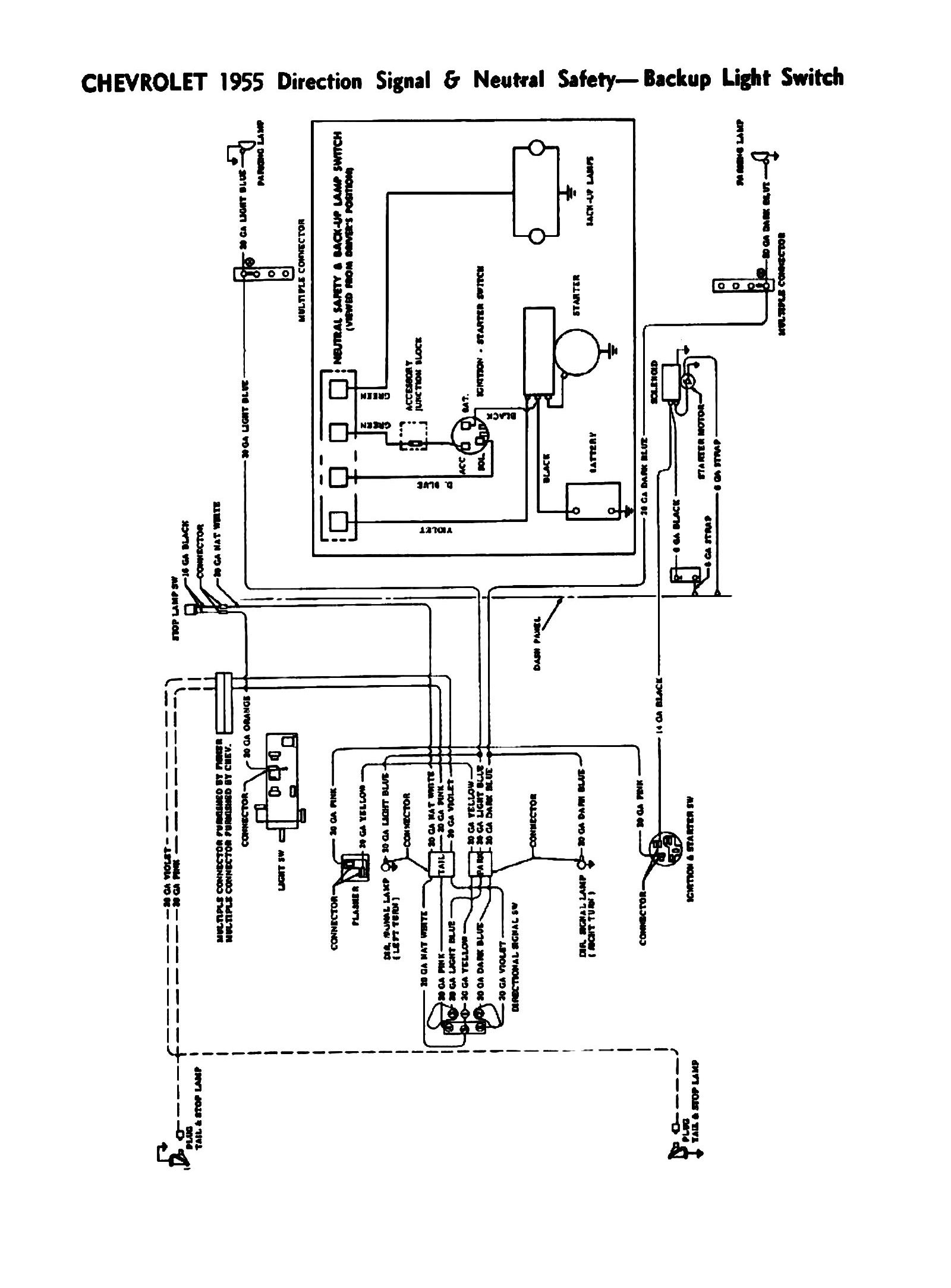
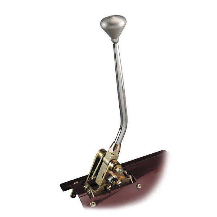
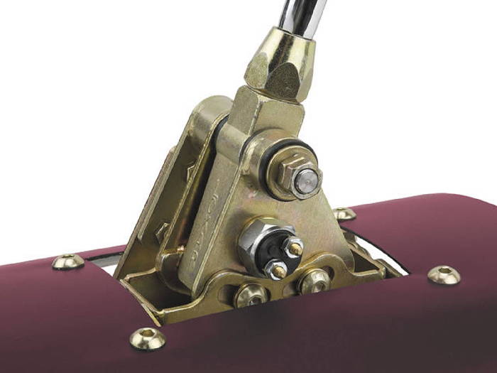
Lokar neutral safety switch wiring diagram. It does not pass current is turned off when the ball is out at its at rest position. 1 so that. If your vehicle is starting in any gear other than park and neutral while using the lokar shifter you must adjust the neutral safety switch. Remove the jumper and wire the switch to the connectors. Lokar neutral safety switch wiring diagram download assortment of lokar neutral safety switch wiring diagram. Ball switch is depressed in park.
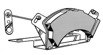
There should be 2 single wire connectors near the lower steering column that will have a jumper between them. Back up light or neutral safety switch kit installation instructions. The neutral safety switch is wired in series with the violet wire from the ignition switch to the starter solenoid. Automatic transmission shifter neutral safety switch adjustment instructions for use with aluminum adjuster plug. For neutral safety switch install double trigger to trans shaft. Back up light or neutral safety switch kit.
Put transmission in park and install double trigger as shown in fig. Brake and clutch pedals and pad covers. The following instructions are for adjusting the neutral safety switch in the lokar automatic transmission shifter using the enclosed aluminum adjuster plug. Switch when transmission is in the neutral position. For use with lokars aluminum adjuster plug. It shows the components of the circuit as simplified forms and the power and signal connections between the devices.
The double trigger should depress the ball. A wiring diagram is a simplified conventional photographic representation of an electric circuit. Link to wiring diagram. The lokar neutral safety switch passes current is turned on when the ball is pushed in. 10924 murdock drive knoxville tn 37932. Toll free 1.


