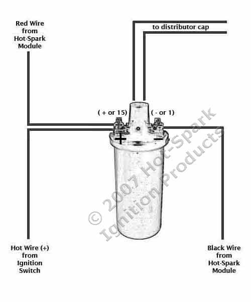
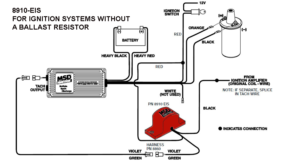
If so with the power on take the cap off and pull the ht lead to coil out of the cap. As for the lumenition first make sure you ve got 12v to the low tension side of the coil.

Optronics Wiring Diagram Lupa Zilong01 Bea Motzner De
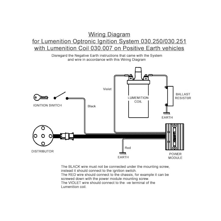
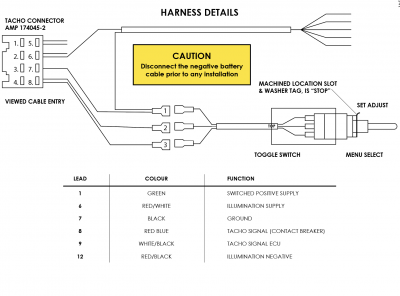
Lumenition wiring diagram. Lumenition optronic ignition system pma 50 power module auth. Lumenition optronicâ ignition system auth. Sjpearce date 111202 ver 22 file pma50 installation page 3 of 6 please note that the brown wire is a violet wire on later units. Place the conductor about 6mm from a safe ground hold with something well insulated 12000v up the. Pooh you cant assume black is ground get a wiring diagram. It is immune to dirt cam wear and dust has no moving parts to wear out and is maintenance free.
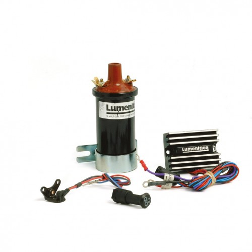
Referring to illustration 2 connect red wire using extension supplied if necessary to either a feed side of ignition terminal f of fuse box. Lumenition ignition system description lumenition optically switched contact breaker replacement ignition systems consist of two basic models the optronic ignition system and the performance ignition system. To test the optical switch the optical switch must be connected to a good power module with a sensitive voltmeter measure the voltage between the blue and. The lumenition standard optronic and performance optronic ignitions convert a large range of contact breaker distributors to electronic ignition. The installation of both systems is straight forward and easily reversible involves no specialist tools. Lumenition optically switched contact breaker replacement ignition systems consist of two basic models the optronic ignition system and the performance ignition system.
Sjp date 110707 ver 23 file pma50 installation v23doc page 3 of 3 3. With more than half a million sold worldwide over 43 years optronic ignitions are the premier contact.


