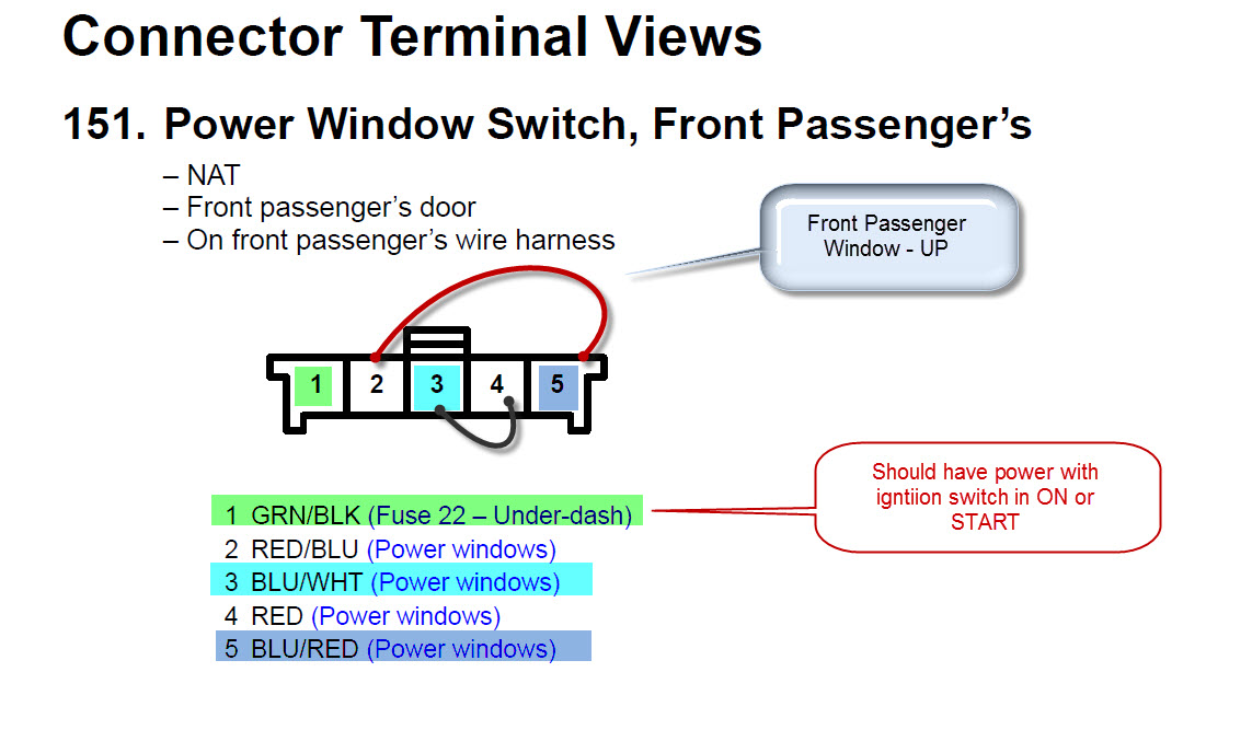
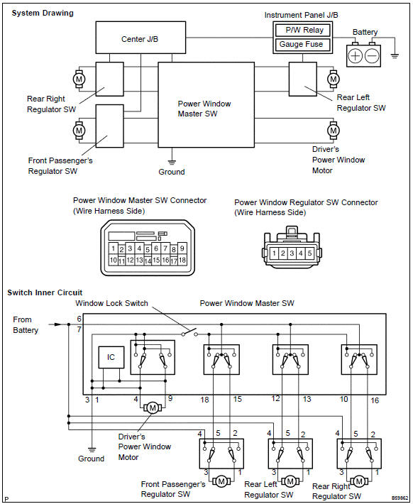
The first wiring diagrams were for the 10 pin switch the other post is for the later 14 pin however as i stated in those posts the 14 pin switch uses a different control method it is not just a switch like the earlier 10 pin ones. Or these terminals can be ignored for non backlit switch banks.

Hostel Wiring Connection With Master Switch
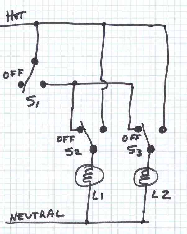
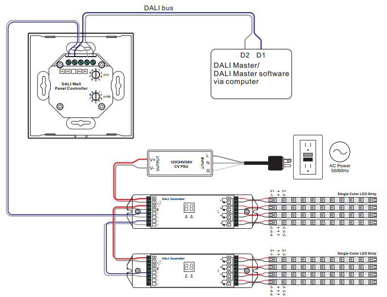
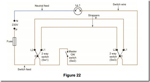
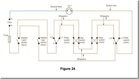
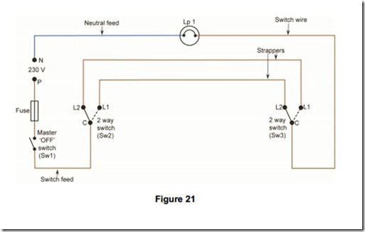
Master switch wiring diagram. Just wiring it up will not work. Make sure the switch in the off position. This following image shows the images of the master switches for the 1933 1936 chevrolet cars. Connect a battery cable from the starter or starter solenoid to one of the 12 switch terminals. Connect a jumper wire from the alternator output terminal to one of the 316. To review a wiring diagram first you have to recognize exactly what basic elements are included in a wiring diagram as well as which photographic symbols are used to represent them.
The image contains of four switch systems they are for the 1933 chevrolet 1934 chevrolet 1935 chevrolet and 1936 chevrolet. Here well go into details on the newer computer controlled. A very detailed wiring diagram analysis video and part of our wiring diagram and automotive electronic series here on this channel. It is a very clear switch system image that can help you study the switches system on your chevrolet car. This electrical question came from. Light switch wiring diagram single pole this light switch wiring diagram page will help you to master one of the most basic do it yourself projects around your house.
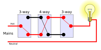
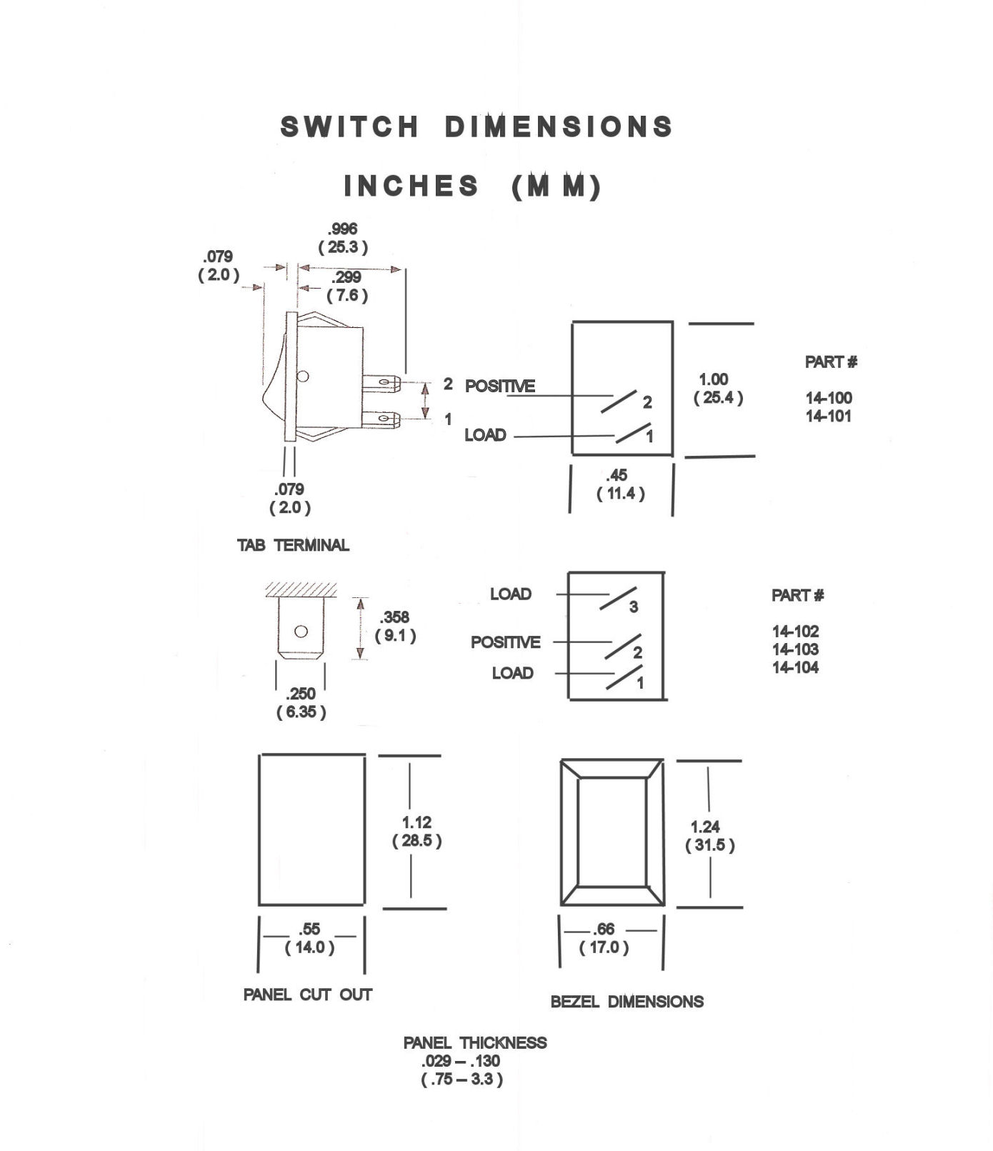
The battery cable should be a minimum of 2 gauge wire. The wiring diagram to the right will show how to wire and power this 12v 20amp on off on 3 way carling contura rocker switch. Master and slave switches are great for multiple switch locations electrical question. The typical aspects in a wiring diagram are ground power supply cable as well as link result gadgets buttons resistors reasoning entrance lights etc. Barry a homeowner from lakeland tn. I need 4 way wiring diagram using master dimmer companion dimmer 1 4 way rocker switch.
Disconnect the positive and negative battery terminal. Whether you have power coming in through the switch or from the lights these switch wiring diagrams will show you the light. I will try to send picture. When wiring this switch you can choose if youd like to illuminate it because of the independent lamp attached to terminals 8 and 7. Weve changed the diagram a bit now to show the start battery running through our new marine battery switch a double pole onoffcombine battery switch like this one is a great choice for a single engine two battery boat wiring system.


