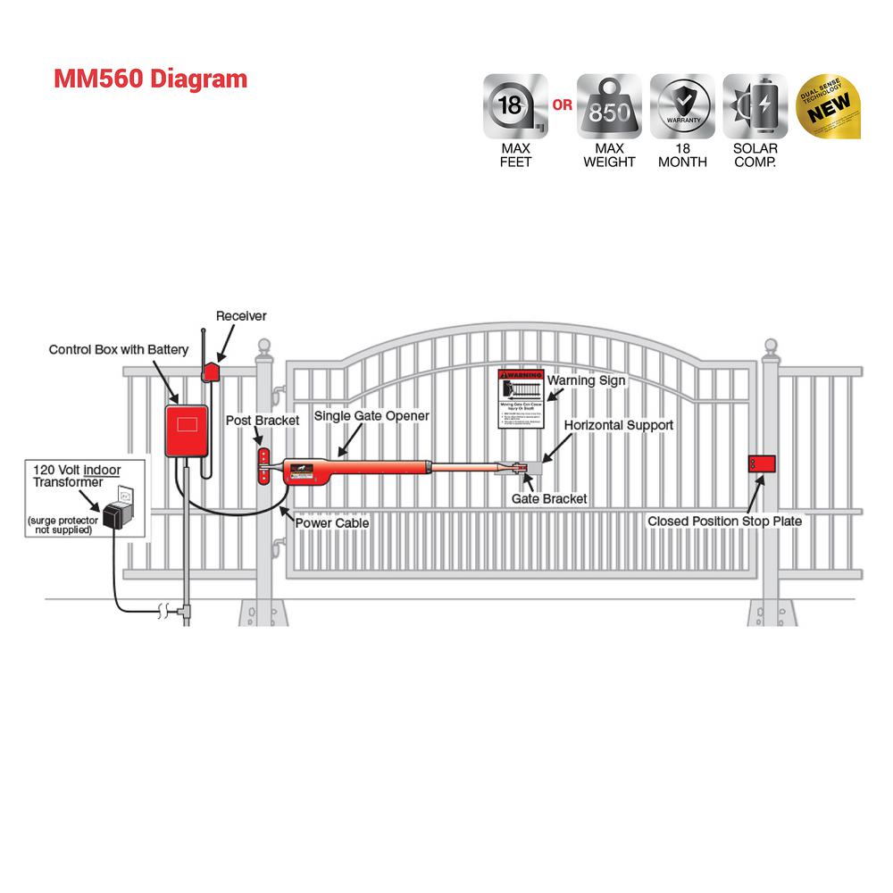
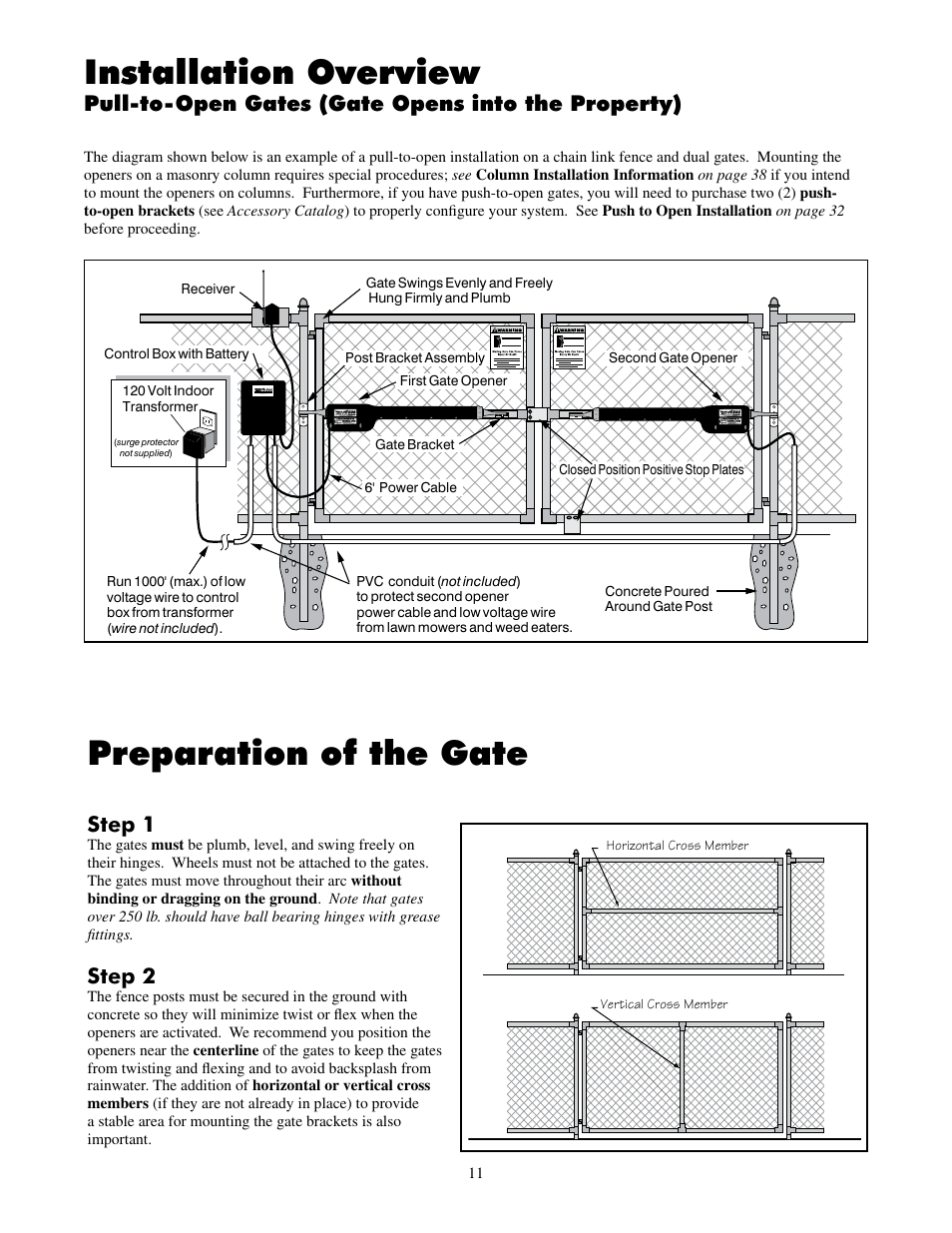
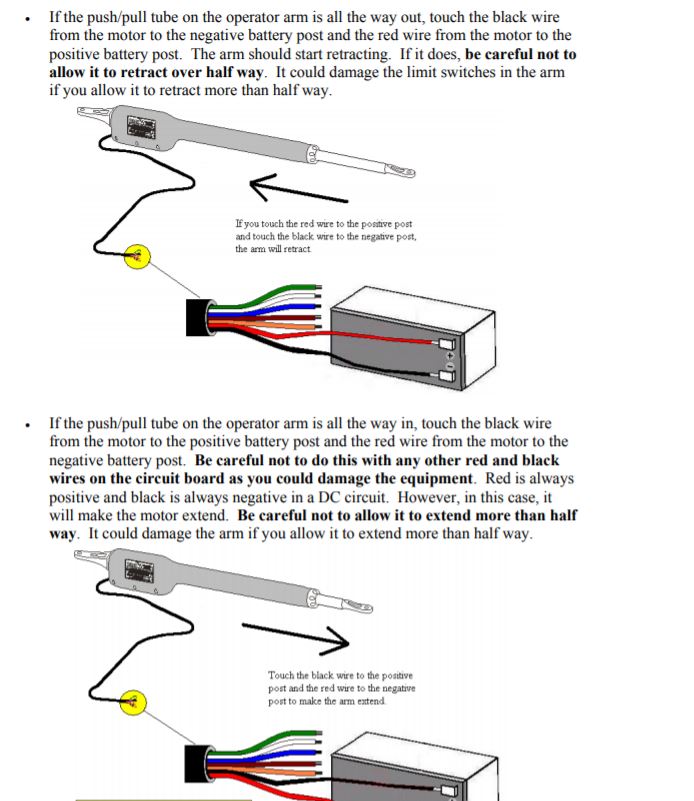
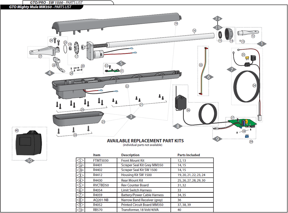
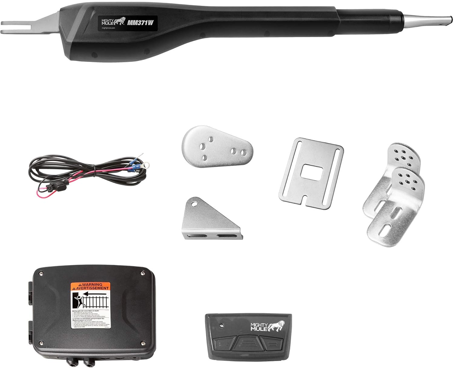
In a dual gate installation the gate opener on the same side of the driveway as the control box is known as the master gate opener and that gate is refered to as the master gate. A wiring diagram is a streamlined standard photographic representation of an electric circuit.

Exit Wand Home Depot Manualzz
Mighty mule gate opener wiring diagram. Mighty mule accessories. A wiring diagram is a simplified standard photographic representation of an electrical circuit. Page 22 at this stage of the installation the openers should be installed on the gate leaves and the open and closed position stops should be in place. 1 855 644 4891. Variety of mighty mule 500 wiring diagram. It reveals the elements of the circuit as simplified shapes and the power and also signal connections in between the gadgets.
Mighty mule 350 gate opener wiring diagram. Assortment of mighty mule gate opener wiring diagram. Mighty mule gate opener wiring diagram. Ii mighty mule mm360 installation instructions product usage the mighty mule gate operator meets all of the safety requirements of a class i residential vehicular gate operator and is intended for use solely with vehicular swing gates in single family residential applications that meet the class i category listed. Installation manual for detailed instructions on gate opener safety and proper use of the gate opener all mighty mule gate openers run off of 12 volt battery power. Gate openers driveway gates garage door openers.
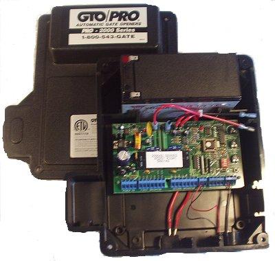
This installation requires the battery charge to be maintained by either a 18 volt transformer or an optional solar panel connected by 16. M f 8am 700pm est. Use the retail search tool to find genuine mighty mule products online or in store. Mighty mule and gto technical support for your mighty mule or gto automatic gate opener and access controls. Electronic gate circuit board circuit board main control board gate opener board power master gate circuit board elite circuit board eagle circuit board crusader circuit board sea circuit board. If you will be using the mighty mule gate lock accessory with your gate opener system the closed position ground stop is required as shown in steps 2 and 3 on the next page.
Monday friday 8am. It reveals the components of the circuit as simplified shapes and the power and signal connections in between the tools. Conversly the gate opener. It reveals the elements of the circuit as simplified forms as well as the power as well as signal links between the tools. Toll free 800 543 1236. Assortment of mighty mule gate opener wiring diagram.
A wiring diagram is a streamlined conventional photographic representation of an electric circuit. For mighty mule fm502 gtopro 3000 and gtopro 4000 dual gate openers note.


