Refrigerant circuit diagrams and thermal sensors y 62 city multi y series outdoor units heat pump. Harman house 1 george street uxbridge middlesex ub8 1qq uk.
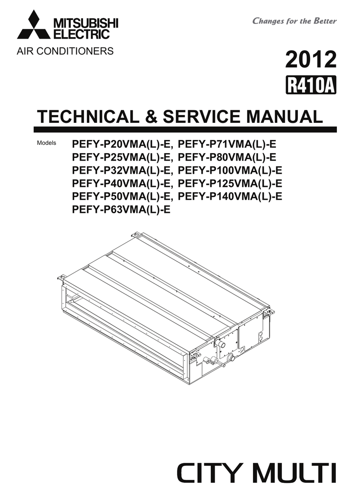
Mitsubishi Electric City Multi Pefy P125vmh E Service Manual
Mitsubishi vrf wiring diagram. Electrical wiring diagrams y 57 6. Tokyo bldg 2 7 3 marunouchi chiyoda ku tokyo 100 8310 japan authorized representative in eu. The control wiring is very simple its basically two 18 gauge wires that go from the thermostat to the fan coils wire 1 so that each zone will have a wire from the thermostat to the fan coilone controller thermostat can control more than one indoor. Mitsubishi electric europe bv. Vrf svn33d en updated outdoor option setting to include manual night set back option. Puy p ygm a bs 8hp 10hp 12hp 14hp 16hp 18hp 20hp 22hp 24hp 26hp 28hp 30hp 32hp 34hp 36hp 38hp 40hp 42hp 44hp 46hp 48hp 50hp y heat pump y cooling only.
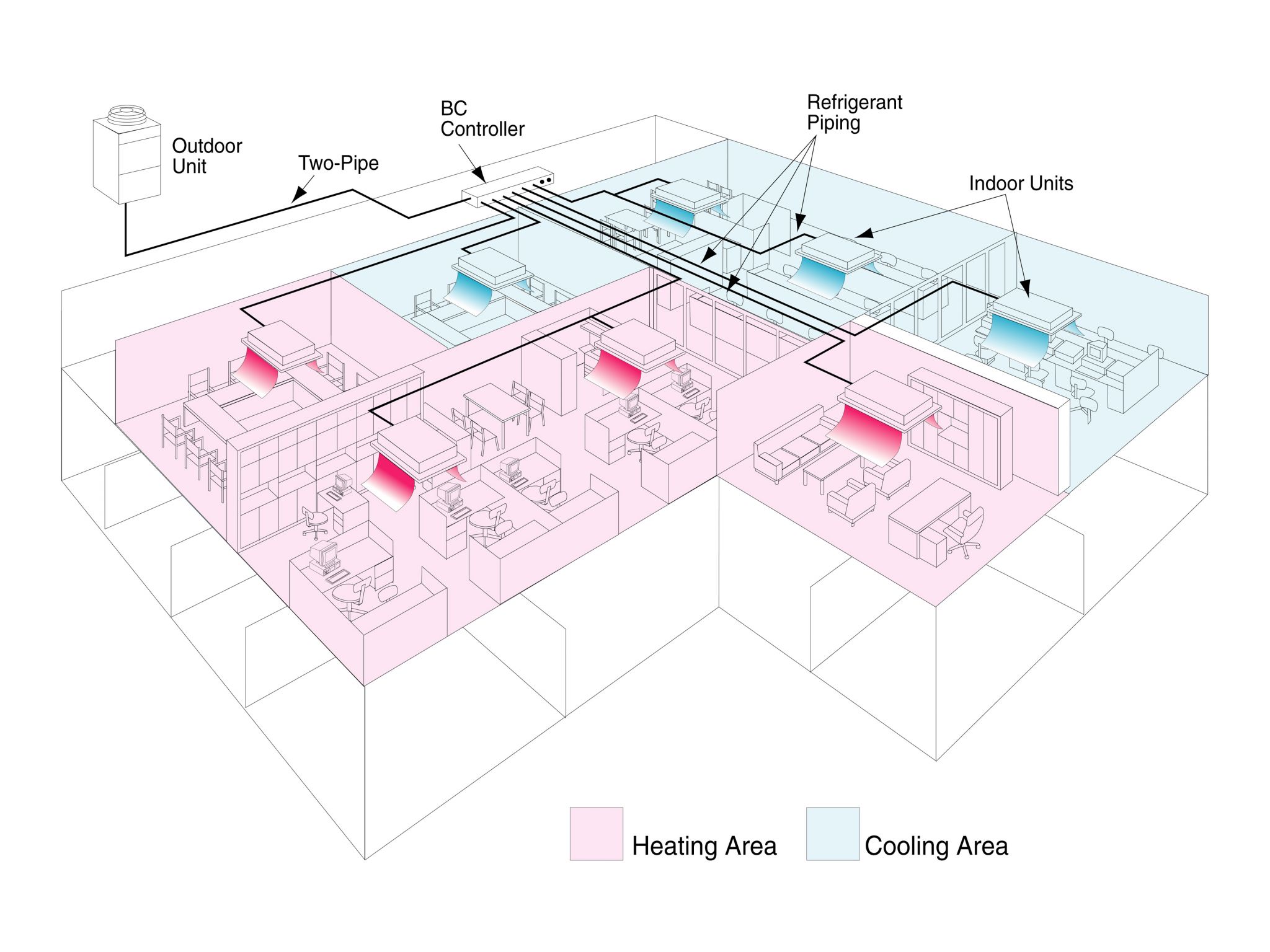
Gb po hg sv cz tr ru gr p nl i e f d sl ro bg hr sw. This vrf system control wiring is for a vrf vrv heat recovery system with single port branch selector boxes. Vrf vrv simple control wiring for a heat recovery system using single port branch selector boxes. Wiring for control hereinafter referred to as transmission shall be 50mm1 58in or more apart from power source source wire in the same conduit be sure to provide designated grounding work to outdoor unit. Vrf system control wiring. Warning personal protective equipment ppe required.
Give some allowance to wiring for electrical part box of indoor and outdoor units because the box is sometimes removed. Vrf svn33b added communication wiring specifications and updated the clearance section. This control wiring layout is similar amongst the other vrf manufactures. Vrf svn33c updated the refrigeration piping section.

