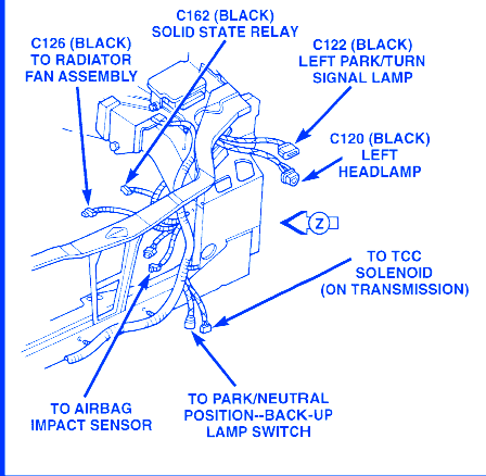
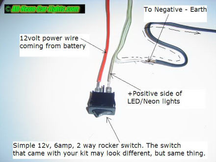
Three wire cable runs between the switches and the outlet. View and download dodge 1997 neon wiring diagrams owners manual online.

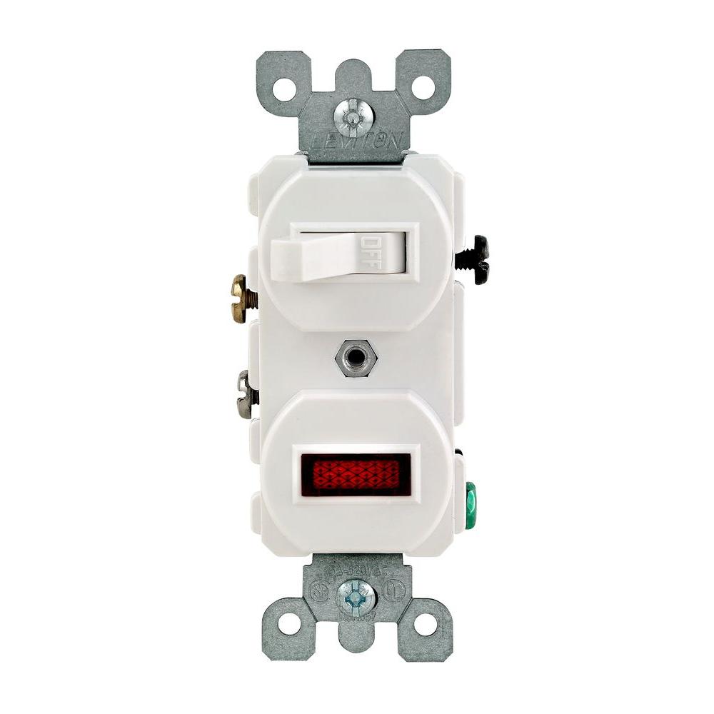
Snap In Neon Rocker Switch Dpst On Off
Neon switch wiring diagram. The front assembly comprises the front support switch modules switch rockers which is mounted to the rear box using 4 captive fixing screws. Variety of neon sign transformer wiring diagram. This circuit is wired the same way as the 3 way lights at this link. It reveals the components of the circuit as simplified shapes and also the power as well as signal connections between the gadgets. In this diagram two 3 way switches control a wall receptacle outlet that may be used to control a lamp from two entrances to a room. 1997 neon wiring diagrams automobile pdf manual download.
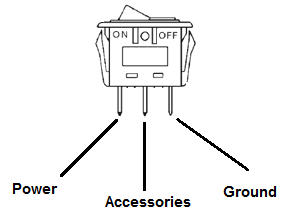
A gasket seal is located on the front edge of rear box. Run switch cycling mode switch switch output output dbor dbyl c206 dbor c206 c101 dbyl dbor heater control pressure. Morning all i have purchased a light switch which has a small neon light built in showing me when the outside light is on or off. 8w 11 2 fuse 8w 11 8 s211 8w 11 8 c206 fused cycling ign. If using a light up switch connect the 3rd connection on the switch to ground. Dodge neon 1999 2000 2001 2002 2003 2004 2005 wiring diagrams service manual download page.
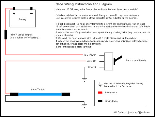
3 way switched outlet wiring. I have placed the 2 wires that come off the neon light both small black wires in the switch one with the brown wire and and one with the blue wire but the neon light is permantley on the switch neon not the the actuall light when the switch is off. Collection of free car service manuals. A wiring diagram is a streamlined standard pictorial depiction of an electric circuit. These are thanks to ptcruzr. Neon accent tube wiring diagram 1 for neons without external transformer.
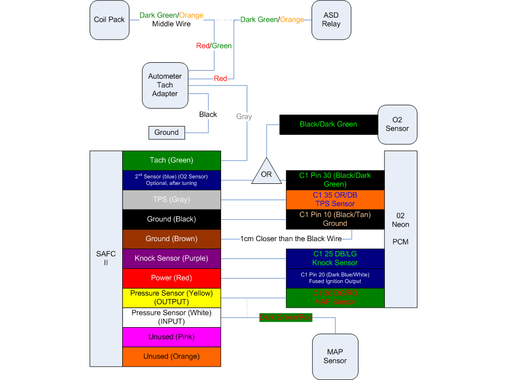
Listed below is the vehicle specific wiring diagram for your car alarm remote starter or keyless entry installation into your 2004 2005 dodge neonthis information outlines the wires location color and polarity to help you identify the proper connection spots in the vehicle. The source is at the sw1 where the hot is connected to.
