The installation voltage and code being used nec nesc will determine how the nrg is applied along with how the system is treated under the nec a 600 volt and under system does not permit l n loads. Green light indicates normal condition and equipment energized.

Spdi Audi 1 8t Wire Diagram July 5 2013
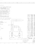
Ngr wiring diagram. Illuminated and non illuminated versions with either incandescent bulbs or leds are available in a variety of popular switching circuits. Assuming the ngr is rated for the direct secondary voltage its inserted between the xo terminal and the groundingearthing system. The components required to monitor an ngr are. Assisted in developing single line diagrams three line diagrams elementary wiring diagrams ewds connection wiring diagrams cwds and relay logic of protection systems. Ngrs are used in an electrical power system to protect the star connected alternatorgenerator or the transformer. Ngr s1 wiring diagram of neutral grounding resistor ground fault relay voltagecurrent set currenttime increment decrement power on ngr fault ground fault sensor fault set mode test reset fail safe relay for neutral resistormonitoring ground fault relay pri earth s1 s2 n s2 earth resistor value 33kv 381 ohms 100kw 66kv 762 ohms 200kw.
Red light indicates ground fault on system. Amber light indicates a ground fault has occured and cleared. Performed technical calculations like protection relay settings short circuit analysis cable sizing neutral grounding resistor ngr sizing and station service. The ngr series us systems are designed for use in us applications and all other parts of the world not including canada. The ngr system is designed for use with littelfuse neutral grounding resistor monitors for complete system grounding and grounding protection. Neutral grounding resistors ngrs limit the fault current when one phase of the system shorts or arcs to ground.
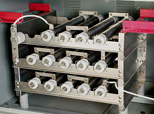
In the event that a ground fault condition exists the ngr typically limits the current to 200 400a though most resistor manufacturers label any resistor that limits the current to 25a or greater as low resistance. Ngrs grounding system provides more benefits. Ngr is constructed by inserting a resistor between the star connected neutral terminal and ground terminal. Figure 2 wiring diagram for gemini. The short form of ngr is neutral grounding resistor. Why ngr neutral grounding resistor are used.
12 se 330 ngr monitoring the se 330 is a microprocessor based ngr monitor that detects ngr failures and ground faults in resistance grounded systems and is compliant with the 2018 ce code. Ngr the field proven ngr offers both european styling and ergonomic design while providing the solid durability that you have come to expect from eaton switches. For applications in canada please use the ngr series canada. Versionng111 19 download4931 stock total files1 file size37494 kb create datejune 15 2015 last updatedfebruary 17 2020 download fileneutral grounding resistors installation and maintenance instructions download. 1 87 resistor normal operation 1. The se 330 measures ngr resistance ngr current and transformer or generator neutral to ground voltage.

