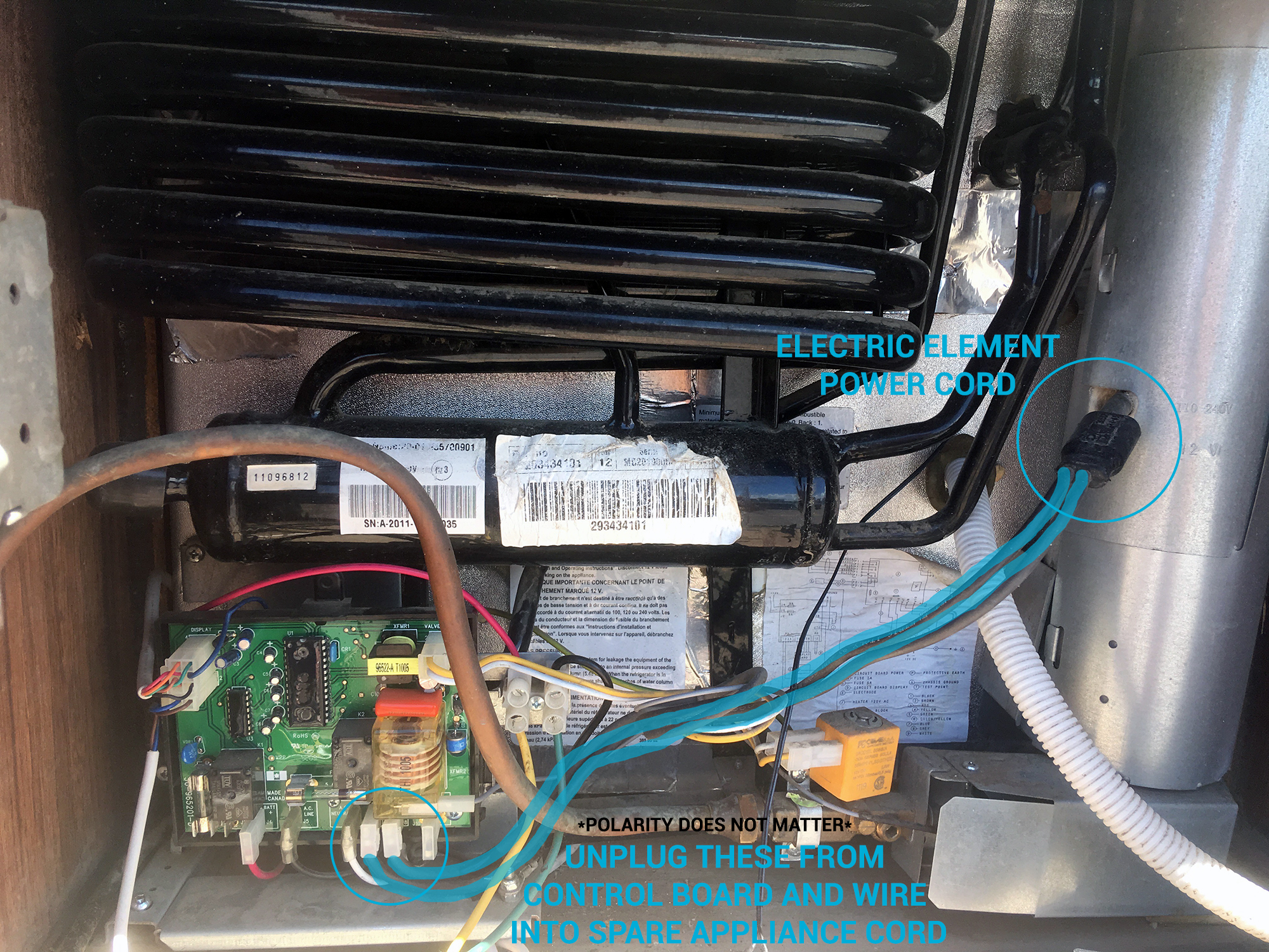
As one can see the factory fan control power originates at the control board the fan also grounds here. Wiring schematics and pictorials.
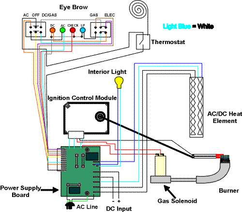
Dave S Place Norcold Electronics 838 And 8310
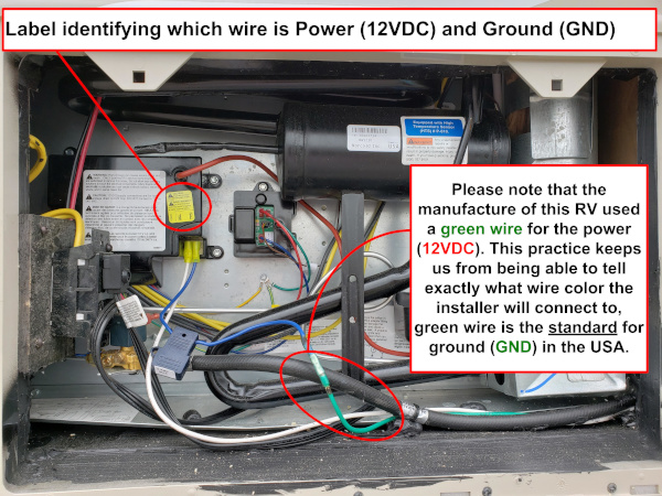
Norcold power board wiring diagram. Norcold power boards for the n611 n621 n641 nx641 and nxa641. Disconnect the wires plugged into the power board on the back of the unit in the following order. This section covers dc power requirement polarity of connections power board dc fuse light assembly light bulb replacement thermistor wire assembly. Owners manual n304 n404 n504. 12vdc positive and negative wires ac power supply cord the solenoid gas valve wire and the sparksense electrode assembly wire. Find best value and selection for your dometic norcold more wiring service diagrams fridge rv search on ebay.
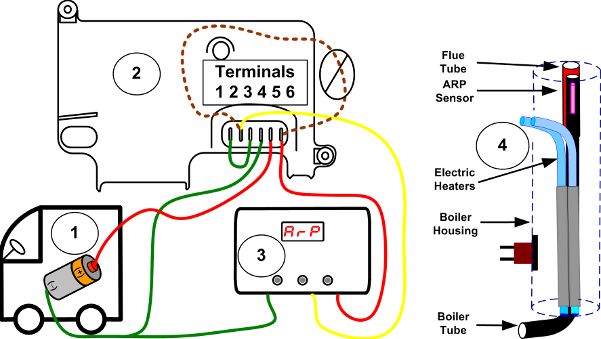
Norcold control box fan wiring. Wiring scheme number 2 1 starting at the rv the rv delivers power to run the fridge and its controls. Please see note in scheme 1 item 1 2 as opposed to drawing 1 the norcold recall box can be wired directly to the norcold control board 4 on the norcold 1210 and other 1200 series fridges. There are two different style power boards made for the n611 n621 and n641 including nx641 and nxa641. Installation manual n304 n404 n504. Turn off ac power and dc power sources before attempting to remove service or repair any of the refrigerators electrical or electronic components.
Grab each wire by the plug not the wire and pull the plug from the socket in the power board. The 12 volt power is routed through the wiring harness to the eyebrow board. Finally the drawing to the left identifies the typical wiring connections for a 1200 series norcold fridge. The newer style board fits all post 2006 n6xx models regardless of the serial number. Installation and owners manual n301 n401 n501. This is the current power board being used in most norcold refrigerators manufactured after this circuit board is the gateway for voltage getting to the various components of the refrigerator55.
Volts dc of the power supply the power is routed directly to the normally open contact of relay k 2 and through the 3 amp fuse to the storage switch for the interior light and high humidity circuits then to the coil of relay k 2. Reservoir replacement dispenser switch replacement and led circuit board replacement. For this wiring scheme the norcold recall remains wired exactly as it was by the norcold. Refrigerator service manual 1200xx120x imxx models about this manual this service manual provides maintenance diagnostic and repair information for norcold incmodel. Each wire is labeled. N301 n304 n401 n404 n501 n504 series.
The older style board pre 2006 has a 16 pin plug connector at the bottom of the board. Do not wet or spray liquids on or near electrical. Do not modify bypass or eliminate any of the refrigerators electrical components electronic circuits or propane gas system components. Norcold reserves the right.


