From long sensing range to oil resistance omrons photoelectric sensing portfolio covers all the features required for advanced applications. Recently i was asked if light on and dark on for a photoelectric sensor was the same as normally open and normally closed.
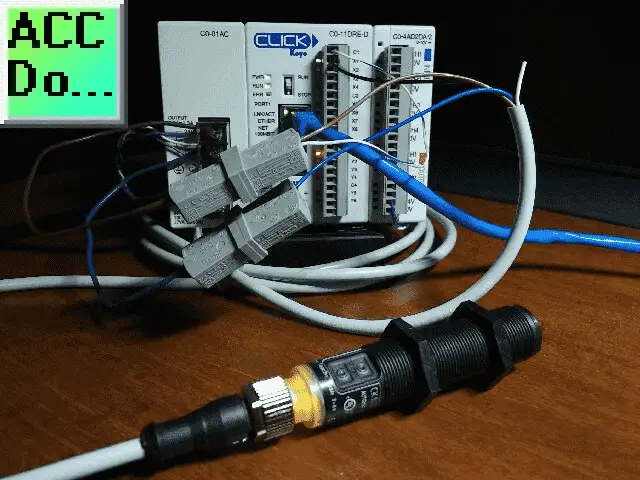
Wiring A Capacitive Proximity Npn Pnp Sensor To The Click Plc
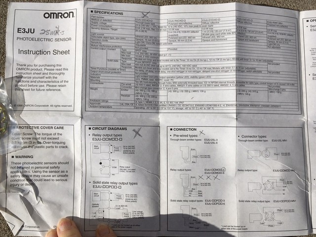
Omron photo eye wiring diagram. Installing an omron e3k photo eye on a viking q7 slide gate operator in arlington texas wwwcontrolledaccessbiz. E3k accessories pdf manual download. When you shine light in the face of the photo eye you should see a increase in resistance and when you cover up the photo eye the resistance should drop to close to zero allowing current to pass. With over 30 years of service experience and a portfolio of industry leading technology our world class team can help you solve problems and sharpen your competitive edge. Electric gate photocells are a crucial part of gate safety. In the world of proximity sensors capacitive sensors and mechanical switches when the target is present the output continue reading photoelectric basics light on or dark on.
Discover how to install photo electric sensors to a liftmaster gate operator. Press and hold teach in. The short answer is yes but i think it justifies more of an explanation. View and download omron e3k instructions online. Compact photoelectric sensor with built in amplifier the standard for photoelectric sensors with a secure track record of one million sold yearly. With the photo eye removed from the circuit and if you have a ohm meter you can test the ohms thru the black and red wire coming out of the photoeye.
Photoelectric sensors technical guide 9. Connection diagram cd 323 l q m hcaet t con detcnneo 1 4 2 bn bk wh bu 3 gy 5 concept of operation kt5 2 teach in teach in static internal signal received dark switching light switching output q output q switching threshold switching threshold internal signal received eelpmax turn rotary switch to teach position. 24 to 240 vac or vdc reflector type photo eye. As shown in the diagram at left the optical system for the limited reflective sensors is designed so that the emitter axis and the receiver axis intersect at the surface of the detected object at an angle θ.


