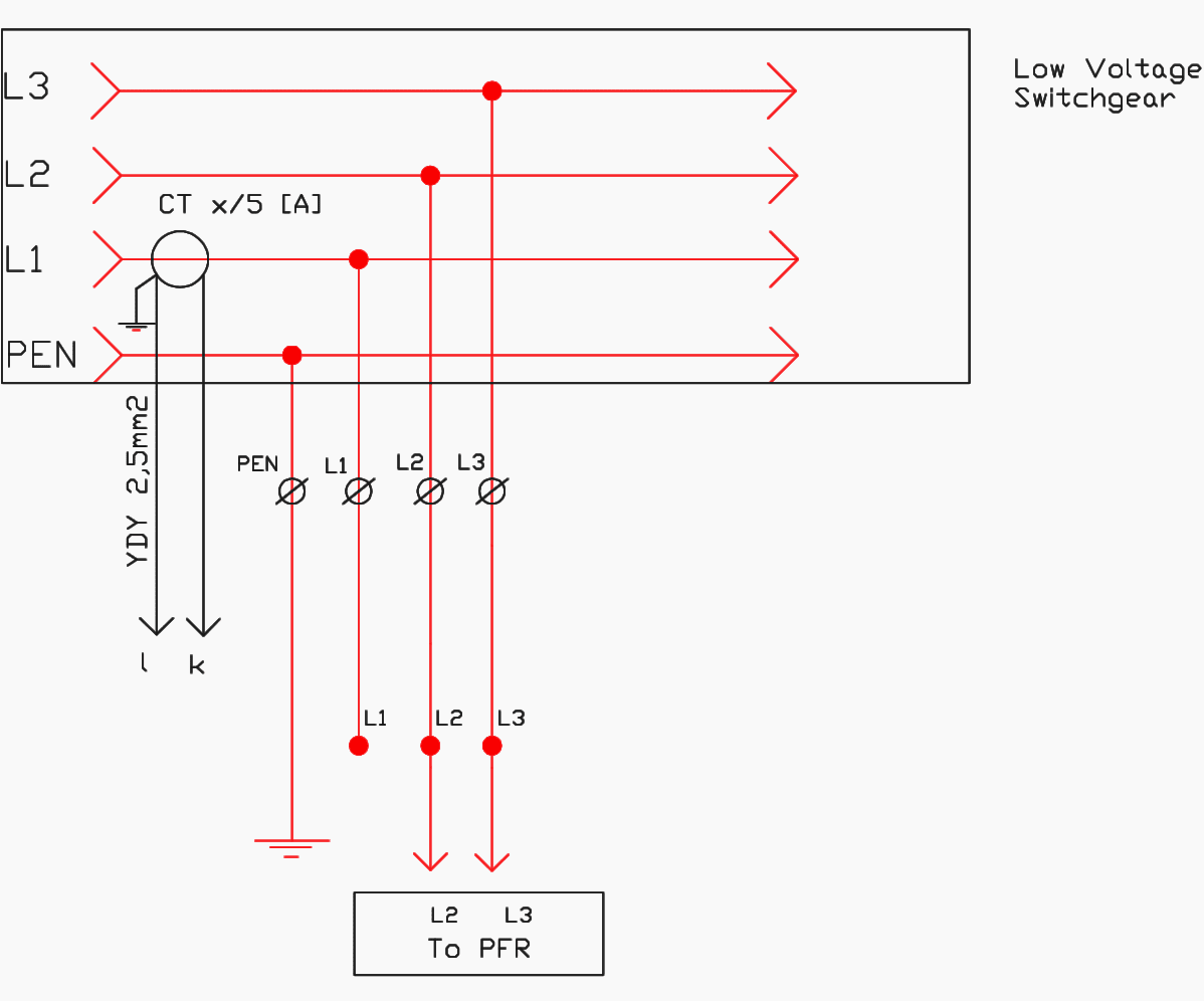
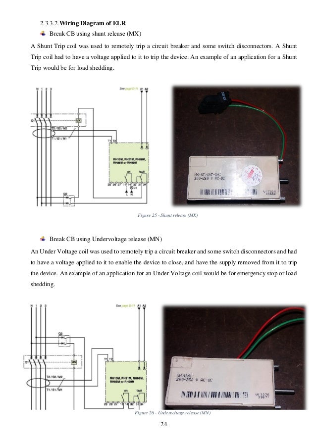
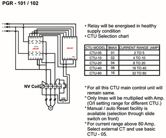
Single phase electricity explained wiring diagram energy meter duration. If a phase failure occurs on l2 or l3 the shunt trip coil will draw power from l1 through the control relay cr contacts and phase failure relay contacts which will c hange state upon detecting a phase failure.
Industrial Project Consultancy Services Gelco Electronic
Pfr wiring diagram. If a phase failure occurs on l1 the control relay cr c ontacts change state. The power can come from either the switch box or the fixture box and a set of electrical switch wiring diagrams will explain each of these scenarios to you clearly. Single pole may sound simple but there are different ways to wire a single pole switch. Fan power and ground. Unlike a pictorial diagram a wiring diagram uses abstract or simplified shapes and lines to show components. Suggested electric fan wiring diagrams converting a 12 volt switch into a ground switch these diagrams show the use of relays onoff sensors onoff switches and onoff fan controllers.
Note due to wrong connection done the above diagram is update in the above diagram i shown the complete method of wiring or connection of phase failure relay diagram with circuit breaker cont actor overload relay push button switches and electric motor however lets talk about this step by step. The plug flow reactor model pfr sometimes called continuous tubular reactor ctr or piston flow reactors is a model used to describe chemical reactions in continuous flowing systems of cylindrical geometry. Pfr has given me a way to link the science of what children need to the art of parenting. The pfr model is used to predict the behavior of chemical reactors of such design so that key reactor variables such as the dimensions of the reactor can be estimated. Blue and brown1 optional the blue wire is the tx transmit and brown is the rx receive wire. Contactor and timer connection in hindi.
The engineering mindset 782582 views. Support diagram and parts list0215 energy data and warranty0416 energy data doe cv4 energy data endviewdiagram updates led lighting parts list and fancoil content0518 dixell operating instructions0518 rev 2 electrical hookups piping locations bolt locations wiring diagrams and parts list0618. Promoting first relationships is such a different way of working with families. Pictorial diagrams are often photos with labels or highly detailed drawings of the physical components. Can be accomplished by using the diagram below. I see this as the key to everything i have wanted to do in my career in early childhood education.
Red and black the red wire will connect to your positive battery terminal and the black wire will connect to your negative battery terminal. The striker powerdata cable consists of four wires. In particular for cps involved families it may be. Switch wiring diagrams a single switch provides switching from one location only.

