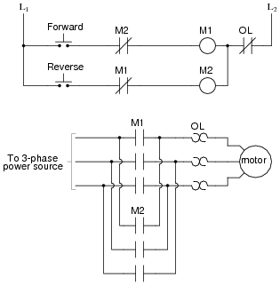
Larger horsepower phase converter systems may be obtained by connecting multiple rotary converters in parallel. Once running the idler motor can then power the load motor.

R 15
Phase a matic wiring diagram. This chart is simplified and cannot reflect all possible applications. Published by admin from january 4 2014. Once running the idler motor can then power the load motor. Is a leading supplier of phase converters voltage stabilizers and transformers for every industry including. The sideway diagram as shown here is to suit the illustration space only. To view just about all photos within 3 phase converter wiring diagram graphics gallery remember to adhere to this particular url.
Mount converter upright with the junction box on the top. E suite 301 palmdale ca. This is necessary for models that are. Restaurant clothing marine nautical hvac refrigeration hotel medical automotive cnc metal woodworking fabrication agriculture welding and a host of other home shop and commercial applications. Wire the load motor in parallel to the idler motor as per method no. Wire the phase a matic static phase converter to the idler motor as described in method no.
At 1 800 962 6976 to verify your phase converter requirements. Easy install of a phase a matic pam 600hd static phase converter to run a 3 phase mill on single phase 220 volt subscribe for more. Phase o matic wiring diagram add a phase wiring diagram collection full size of wiring diagram phone line wiring. Wire the phase a matic static phase converter to the idler. Size fuses and wires on the single phase side as appropriate for the motors rated amperage. Size fuses and wires on the single phase side as appropriate for the motors rated amperage.
Phase a matic wiring diagram wire the phase a matic static phase converter to the idler. Phase o matic wiring diagram name. Wire the load motor in parallel to the idler motor as per method no. Phase a matic for smaller single phase breaker qualifications. This graphic phase a matic static phase converter installation regarding 3 phase converter wiring diagram earlier mentioned can be classed having. Size fuses and wires on the single phase side as appropriate for the motors rated amperage.
Wire the load motor in parallel to the idler motor as per method no. Once running the idler motor can then power the load motor.


