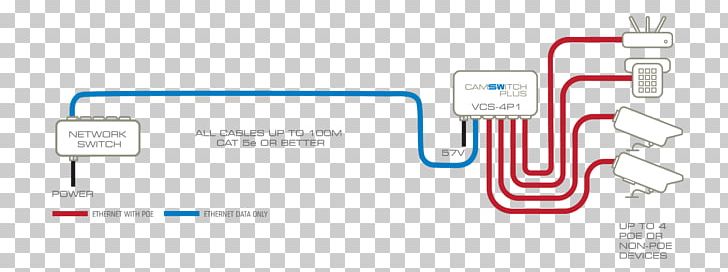
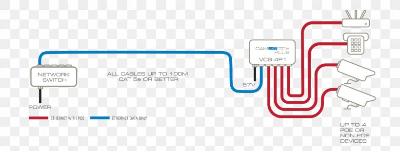
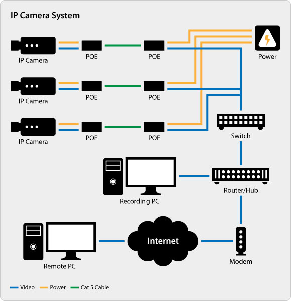
The picture below shows the tp link poe injector that can be used to power up ip cameras using the international standard ieee 8023af for up to 100m. Also both poe power over internet and non poe cameras can be connected to the nvr system based on its design.
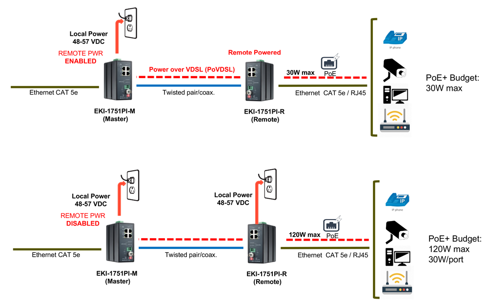
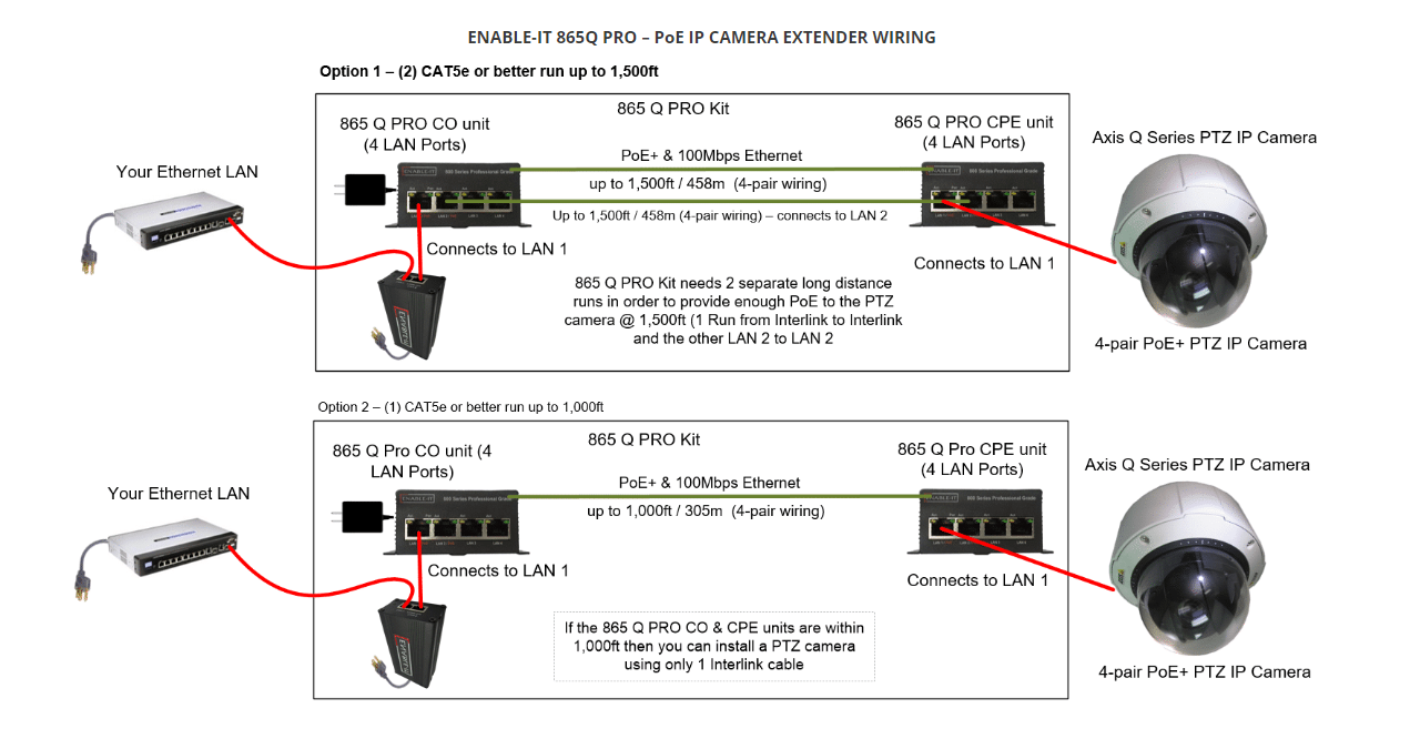
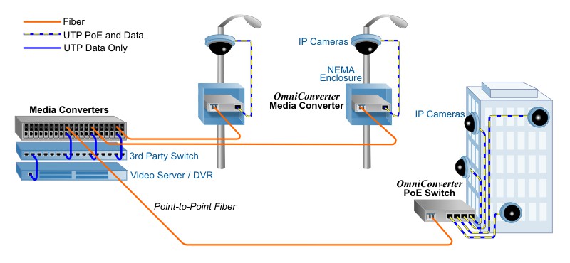
Installing Ip Cameras More Than 100 Meters From The Closest
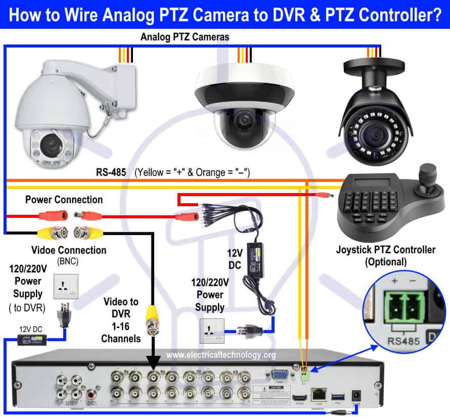
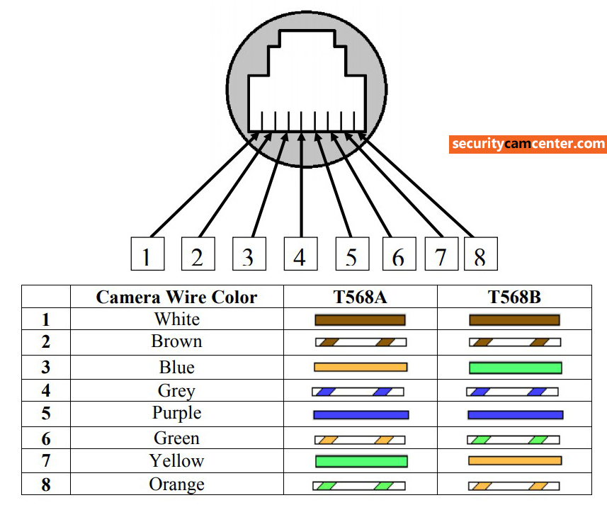
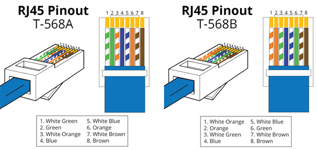
Poe wiring diagram for cameras. Poe ip camera wiring diagram power over ethernet poe technology enables powering ip surveillance cameras through the transfer of dc electrical and saves money by eliminating the expense and difficulty of direct electrical with poe power can be supplied either by a poe switch or from a poe injector a small power supply placed between a switch and a powered poe device. There are just two things which are going to be present in almost any poe ip camera wiring diagram. Take a look at the picture below on the left side its the rj45 pinout t 568b and the right side the dahua ip camera poe pinout color coded wiring diagram. In some nvrs there is no built in poe system and you will have to. Components of poe ip camera wiring diagram and some tips. Keep in mind that only ip camera internet protocol can be used with nvr system as compared to dvr where analog camera are usedmoreover nvr is a wire or wireless system where dvr doesnt support wireless system.
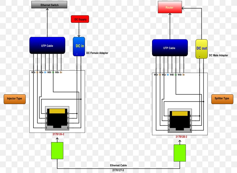
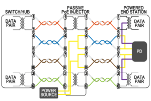
Pinout of power over ethernet poe and layout of 8 pin rj45 8p8c female connector and 8 pin rj45 8p8c male connectorpower over ethernet is a technology that allows ip telephones wireless lan access points security network cameras and other ip based terminals to receive power in parallel to data over the existing cat 5 ethernet infrastructure without the need to make any modifications. Make the connection as shown on the illustration. The first element is emblem that indicate electric element from the circuit. If you are concerned about how to wire poe cameras spending just a few bucks thats the way to go since you can buy a poe injector for less than 30. A circuit is generally composed by various components. For example grey wire goes to pin 8 brown wire goes to pin 2 blue goes to pin 1 and so on.
The other thing you will see a circuit diagram would be lines.

