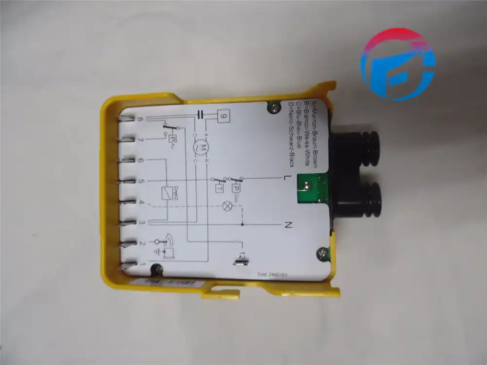
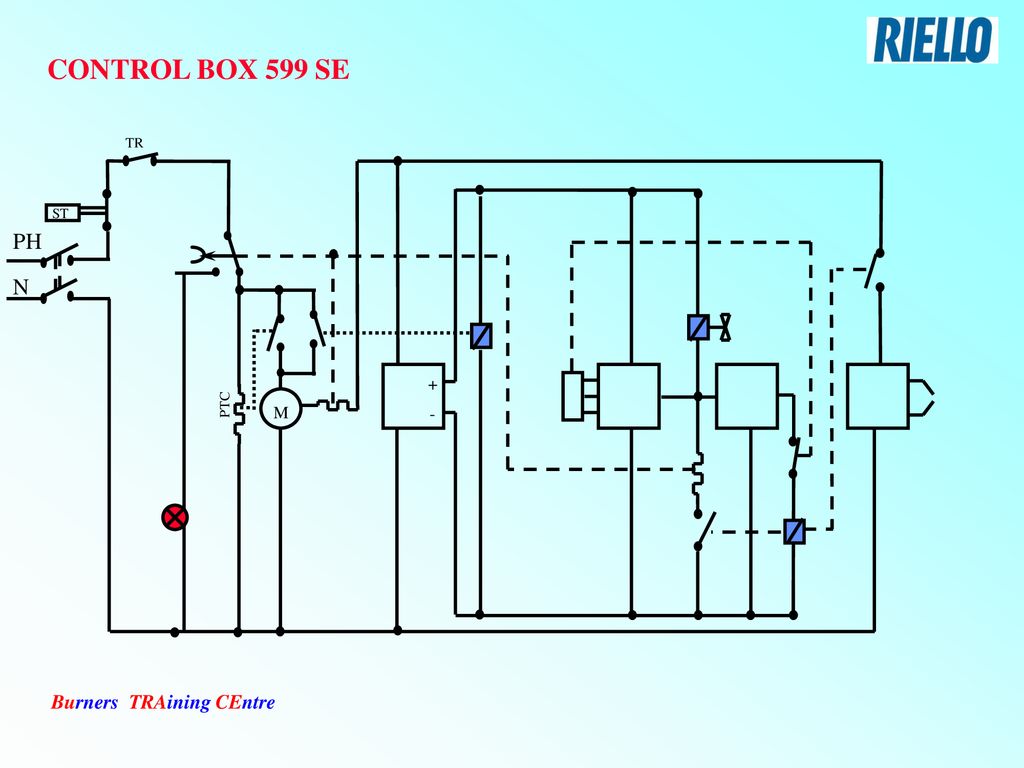
Electronic air shutter requires a constant 120v power supply to the aux terminal failure to provide this will result 1n no burner operation or air shutter will not close. Application field wiring wiring diagram shown below for standard riello 530 sec primary control box installation note.
Riello Rl70 Manual
Riello control box wiring diagram. Permanent lo light check polarity check no feedback on remote lo line then cx box. If faulty then replace coil. Via pilade riello 7 37045 legnago vr product. Electronic air shutter requires a constant 120v power supply to the aux terminal failure to provide this will result 1n no burner operation or air shutter will not close. Gad 2009142ec gas devices directive md 200642ec machine directive. En 676 en 12100 and according to the european directives.
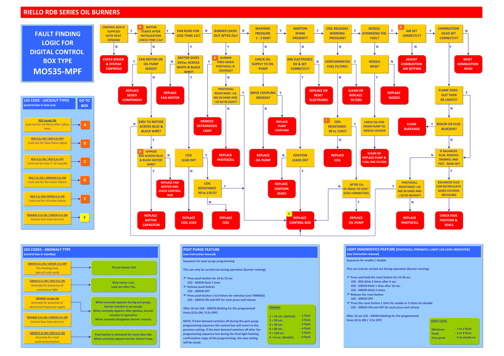
Electronic air shutter requires a constant 120v power supply to the aux terminal failure to provide this will result in no burner operation or air shutter will not close. Application field wiring riello 530 sec 24 v application field wiring riello 530 sec 24v primary control direct line low voltage voltage 1 2 0 v 1 2 0 v fuse 15a fuse 15a line safety line safety switch switch operating limit switch 24v operating safety safety. Control box in standby fault finding logic for digital control box type mo535mpf riello rdb series oil burners red 05s on red 05s off lockout for false flame signal red 02son red off lockout for max n of recycles red 25s on orange 05s on lockout fan motor failure red steady on. Application field wiring wiring diagram shown below for standard riello 530 sec primary control installation note. Coil voltage 27 30v dc at ignition 3vdc on running. The new rmg 508se control box fitted with the reset button extension replaces control box 508se but does not replace the old 505se version.
Rbo522 control box riello part n o. Control box rmg 508se does not have a delay time between the second stage terminal 14 and third stage terminal 11 as shown on the control boxs diagram under the cover consequently you will need to. Check voltage on white wire to. Control base for 508509 riello part n o. If it fires after 12 secs and then locks out after 5 secs the photocell is faulty. Re fit control box and fire up burner.
Fault finding logic for control box type 535 seld rdb series oil burners. Riello 40 gs20d these products are in compliance with the following technical standards. Control box base riello part n o. 3 t 4 operating limit device. Boiler diagrams spare parts and user manuals for riello riello control boxes control boxes 24 hour delivery on genuine manufacturer boiler spares 30 day money back guarantee. Check resistance of the solenoid coil.
2 kohms with a strong light ol in dark 08 ma. Application field wiring wiring diagram shown below for standard riello 530 sec primary control box installation note. Blue and brown wires 147 kohms and blue and black wires 14 ohms readings should be within 10 of these figures. Forced draught gas burner model.

