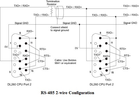
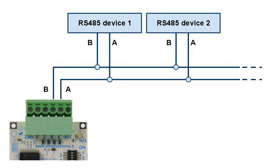
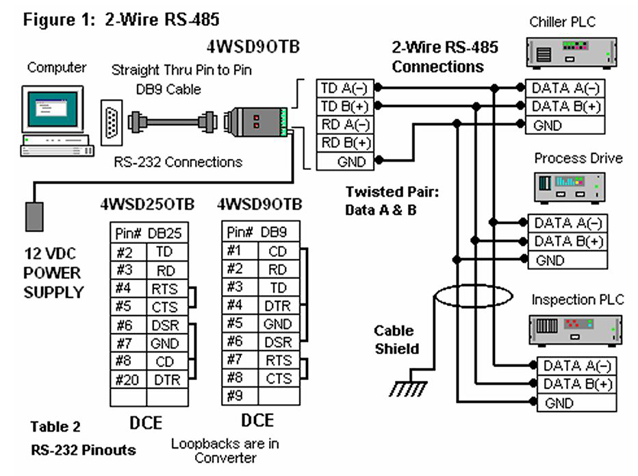
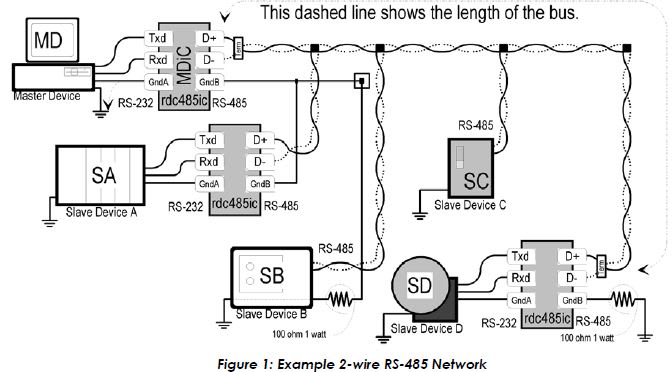
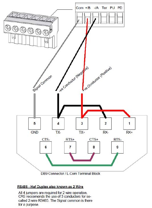
Rs 485 wiring diagram. Half duplex 2 wire for 2 wire transmission you will need to short the transmit txd and receive rxd signals together on the rs 485 port.
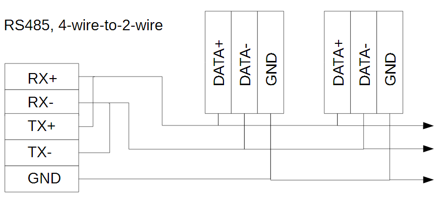
1 Wire Gateway
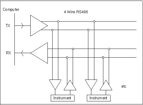
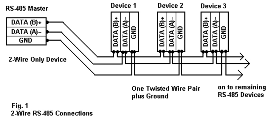
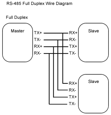
Rs485 2 wire wiring diagram. Rs485 half duplex wiring diagram two wire rs networks operate in half duplex mode on one twisted pair plus a the following diagram shows the daisy chain topology. In this arrangement the computer sends data out over a single rs485 pair of wires to many instruments. Figure 4 is a pin diagram for both 25 pin rs485 pinout half duplex and full duplex pinout connectors. If using a pre made cable verify wire color to pin location when in doubt ring it out. 4 wire slave 2 wire daisy chain wiring twisted pair plus shield belden 9841 cable or equivalent. The corresponding pins will depend on your devices user manual and the rs 485 cable connector type.
The txd and txd lines carry transmit data while the rxd and rxd contain the receive data. Here is a picture gallery about rs485 2 wire connection diagram complete with the description of the image please find the image you need. Two switches are set for 2w or to the 2 wire rs 485 mode. Wiring diagram for cars with regard to rs485 2 wire connection diagram image size 500 x 500 px and to view image details please click the image. Check the data sheet schematic or block diagram. Figure 3 is an rs485 wiring diagram for rs485 pinout db9 connectors.
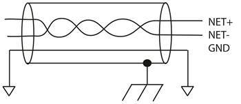
Figure 3 applies to most bb rs 485 converters or serial cards that can be set for 2 wire or 4 wire operation and for some 2 wire converters that use the same circuit board for the rs 422 model. Many of the more common problems associated with rs485 network stability can be mitigated by following these recommendations for wiring termination and line bias. In addition to the data wires it is worth considering whether to use a shielded cable braidfoil connected to signal earth. It never reads any data back. Write only 4 wire full duplex and 2 wire half duplex. The distances these signals are carried is greater due to differential signals.
The items in this document are presented as points of interest to designers and installers of modbus networks. Three arrangements are commonplace. Rs485 recommended wiring. The following diagrams show the recommended schemas for 2 wire and 4 wire configurations for farsync cards such as the farsync flex and farsync t2ee. Mixing rs 485 2 wire 4 wire systems using cnv 100 technical note tn 106 may 2016 introduction the eiatia 485 standard by the telecommunications industry association more. The other signals of the serial port are not used.
Rs 2 wire half duplex or rs 4 wire full duplex or rs 4 wire full duplex follow the wiring diagram in figure1 to connect to a 2 wire half duplex. For ni serial hardware connector pinout diagrams refer to the serial quick reference guide. Party mode interface party mode is an advanced communications configuration requiring a working knowledge of the ansitiaeia 422 and tiaeia 485 standards as well as sem mdrive products and the mcode programming and control language.


