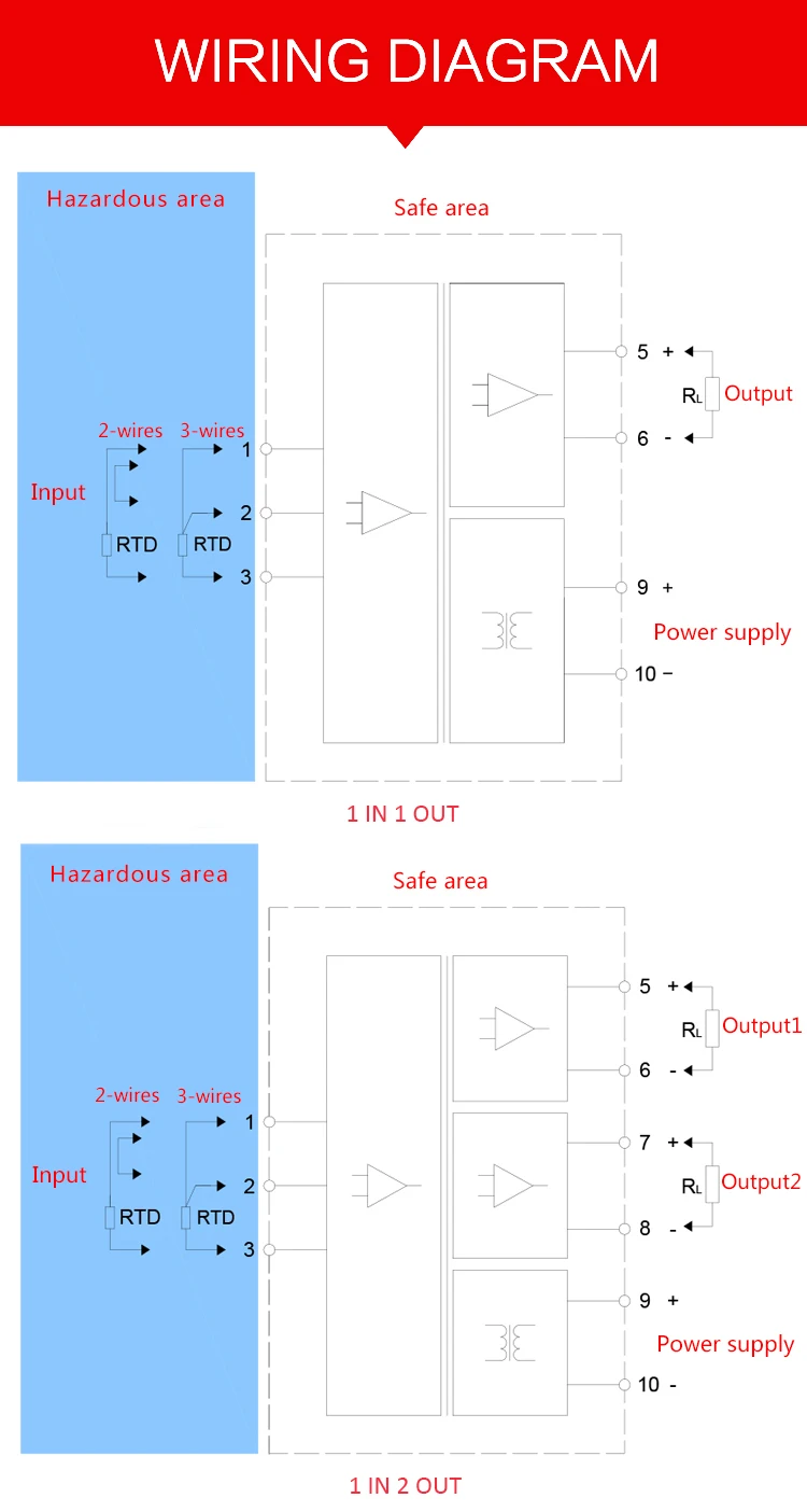
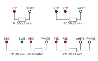
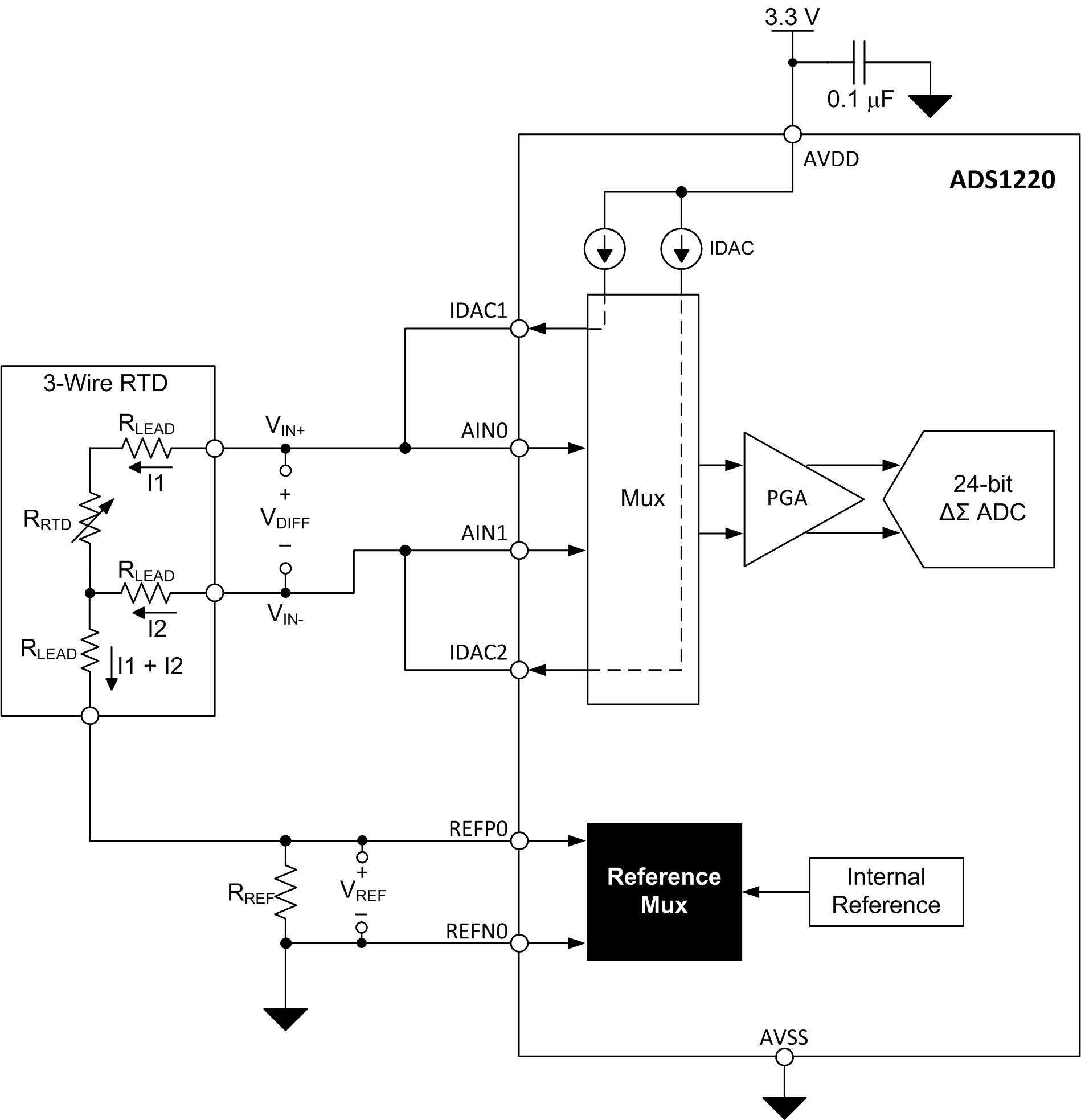
Assortment of rtd pt100 3 wire wiring diagram. A1b1 a2b2 and c1c2.
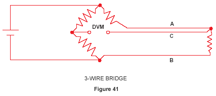
Rtd Elements And Sensors Introduction And Tables
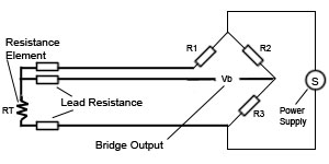
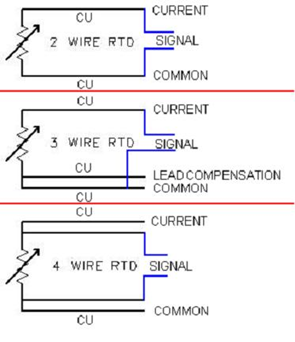
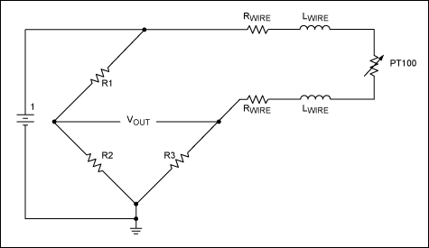
Rtd pt100 3 wire wiring diagram. Wire pt100 wiring diagram for 3 wire pt100 wiring diagram by admin from the thousands of pictures on the web concerning 3 wire pt100 wiring diagram selects the very best series with ideal resolution just for you and now this photos is one among photos choices in your best photographs gallery concerning 3 wire pt100 wiring diagram. There are 2 wiring methods for the rtd module and pt100 temperature sensors two wire and three wire connections. Pt100 wiring methods 2 3 or 4 wire. It shows the components of the circuit as streamlined shapes and also the power and also signal links between the gadgets. It shows how a electrical wires are interconnected which enable it to also show where fixtures and components may be coupled to the system. It shows the components of the circuit as streamlined forms as well as the power and also signal links between the tools.
A wiring diagram is a straightforward visual representation of the physical connections and physical layout of your electrical system or circuit. Rtd pt100 3 wire wiring diagram images. Rtd pt100 3 wire wiring diagram what is a wiring diagram. When wiring with two wires first jumper across a1 and b1and a2 and b2 respectively then connect pt100 sensors and to the rtd module according to the following diagram on the left. The wiring of a pt100 temperature is different to other temperature sensors in particular thermocouplesit is important to get the wiring of your sensor correct otherwise the measuring instrument may give an incorrect reading or no reading at all. A wiring diagram is a simplified conventional pictorial depiction of an electrical circuit.
A wiring diagram is a streamlined standard photographic depiction of an electrical circuit. Assortment of 3 wire rtd wiring diagram.
.jpg)
