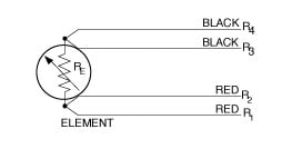
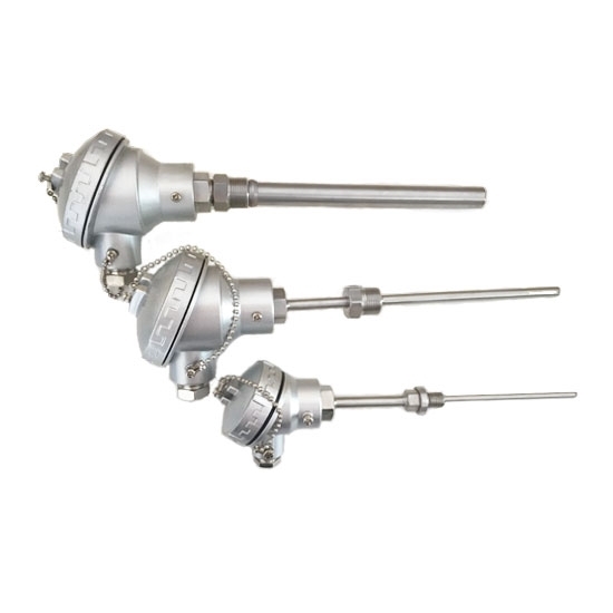
Sensors using the 3 wire construction are the most common design found in industrial process and monitoring applications. A wiring diagram is a streamlined standard photographic depiction of an electrical circuit.
.jpg)
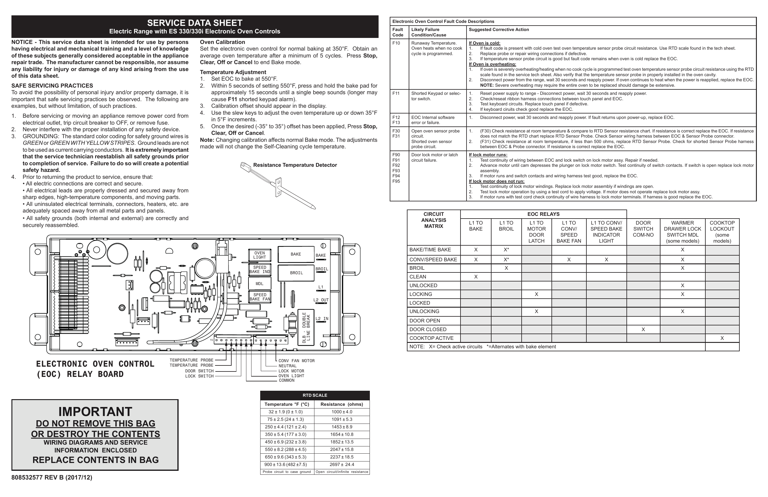
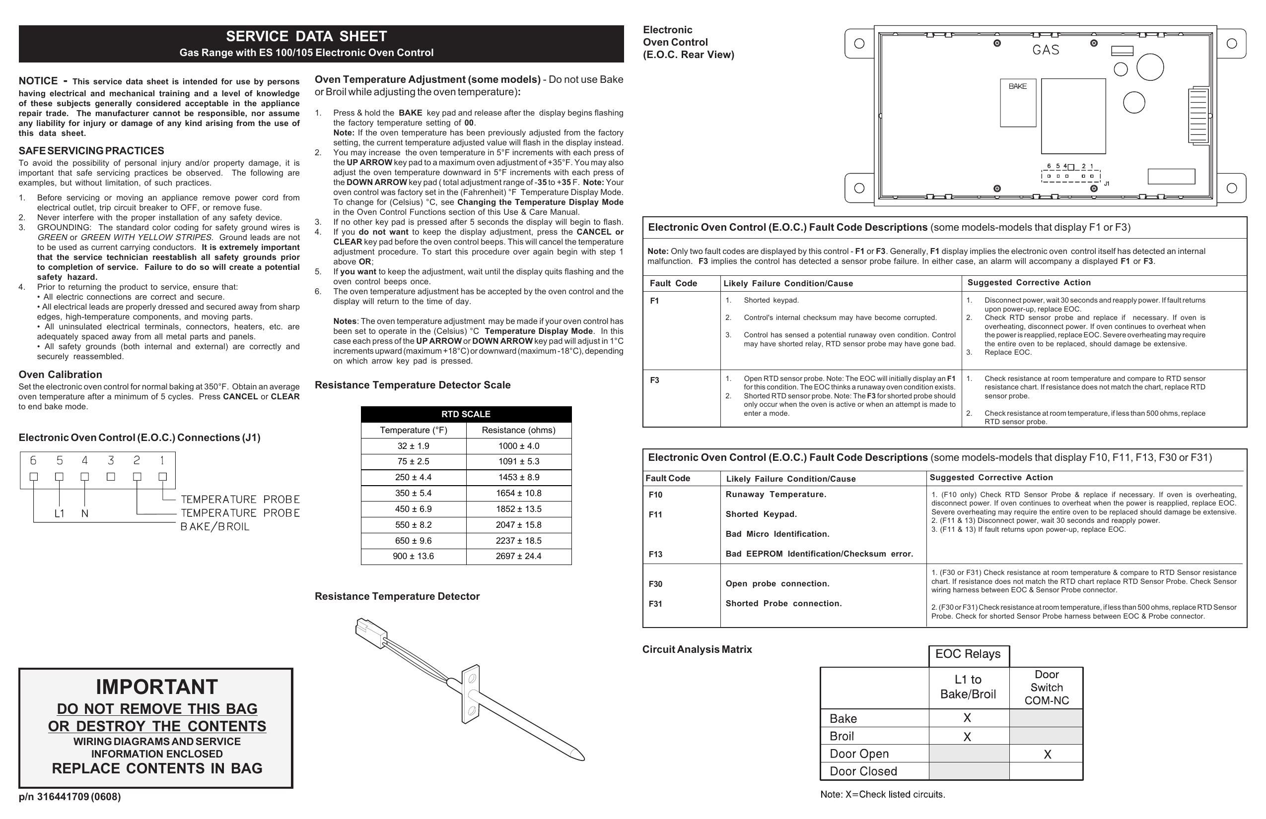
Principle Of Operation Of A Resistance Temperature Detector Rtd
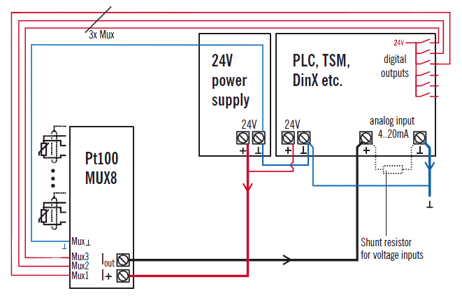
Rtd sensor wiring diagram. The following connection diagrams illustrate how to connect various rtd types to your daq device. R1 r2 and r3 are fixed resistors. A1b1 a2b2 and c1c2. When wiring with two wires first jumper across a1 and b1and a2 and b2 respectively then connect pt100 sensors and to the rtd module according to the following diagram on the left. The resistance vs temperature relationship is well known and is repeatable over time. There are 2 wiring methods for the rtd module and pt100 temperature sensors two wire and three wire connections.
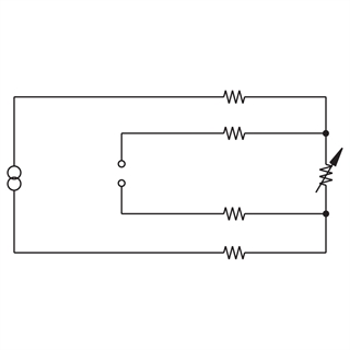
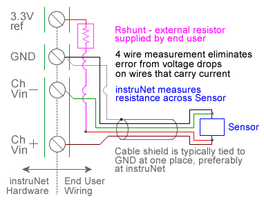
An rtd is a passive device. Shown is a 2 wire rtd connected to a typical wheatstone bridge circuit. 4 wire rtd signal connection connect each of the red leads on the positive side of the resistive element to the excitation positive and channel positive on the daq device. Otherwise errors can result. Rtd technical data see also. Normally a 2 wire rtd will lose accuracy due to the resistance in the cable which can be thousands of feet long.
The lead wire resistance is factored out as long as all of the lead wires have the same resistance. A 2 wire rtd configuration is the most useful with high resistance sensors or in applications where a great deal of accuracy is not required. It does not produce an output on its own. The best configuration for a specific application depends on a number of factors however the sensor configuration must match with transmitter otherwise leadwire resistance cancellation circuitry. This is the easiest wiring you can just use either terminal block slot on the sides for each wire. Wellborn assortment of rtd pt100 3 wire wiring diagram.
The 3 wire rtd uses 1 additional wire and the 4 wire rtd uses 2 additional wires to compensate for the wire resistance. The resistance increases as the temperature of the sensor increases. Es is the supply voltage. Connect the black or white lead on the negative side for the resistive. Eo is the output voltage. In this article the possible wiring alternatives for rtd probes are explained.
In this uncompensated circuit lead resistance l1 and l2 add. An rtd resistance temperature detector is a sensor whose resistance changes as its temperature changes. It shows the components of the circuit as streamlined shapes and also the power and also signal links between the gadgets. Difference between 2 wire rtd 3 wire rtd and 4 wire rtds rtds resistance temperature detectors are offered with 2 3 or 4 lead configuration. 3 wire rtd connections the 3 wire rtd configuration is the most commonly used rtd circuit design and can be seen in industrial process and monitoring applications. Then either solder closed the jumpers next to the rtd terminal block or put little wires in the right and left terminal blocks to short them together.
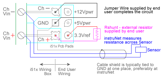
June 17 2019 by larry a. Generally speaking field devices have inputs for 3 wire sensors to. And rt is the rtd.
Gallery of Rtd Sensor Wiring Diagram
.jpg)