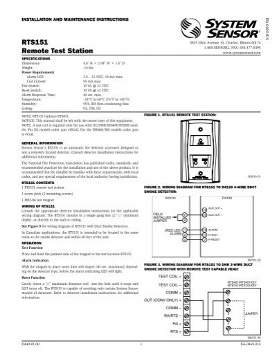
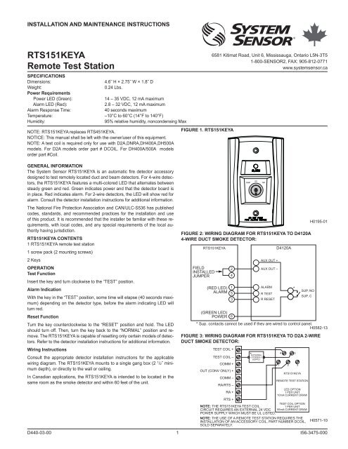
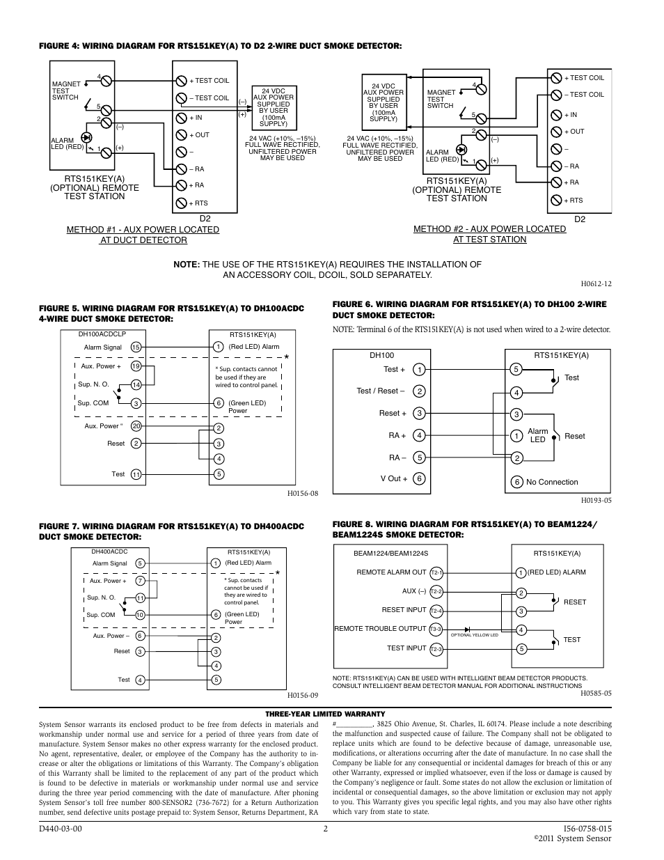
Figure 4 2 wire duct smoke detector powered from the initiating device circuit wiring diagram figure 5 illustrates the wiring diagram for 2 wire duct smoke detector to the rts151rts151key remote test station. The rts151 mounts to a single gang box 2 12 minimum depth or directly to the wall or ceiling.
System Sensor Rts151key A User Manual Page 2 2 Also
Rts151 wiring diagram. In canadian applications the rts151key a is intended to be located in the. The rts151keya mounts to a single gang box 2 1 2 mini mum depth or directly to the wall or ceiling. The use of either the rts151 or rts151key. In canadian applications the rts151 is intended to be located in the same room as the smoke detector and within 60 feet of the unit. In canadian applications the rts151 is intended to be located in the same room as the smoke detector and within 60 feet of the unit. Figure 5 2 wire duct smoke detector to rts151rts151key wiring diagram important notes.
The rts151 mounts to a single gang box 2 12 minimum depth or directly to the wall or ceiling. See figure 8 for wiring diagram of rts151 with duct smoke detectors. Rts151rts151key jumper 4 5 3 2 1 test coil. The rts151key a mounts to a single gang box 2 mum depth or directly to the wall or ceiling. The rts151key mounts to a single gang box 2 12 minimum depth or directly to the wall or ceiling. See figure 8 for wiring diagram of rts151 with duct smoke detectors.
In canadian applications the rts151key is intended to be located in the same room as the smoke detector and within 60 feet of. Wiring instructions consult the appropriate detector installation instructions for the applicable wiring diagram. In canadian applications the rts151keya is intended to be located in the same room as the smoke detector and within 60 feet of the unit.


