San ace 40 mm san ace 40 for 1u server most appropriate for 19 inch rack mount 1u 445mm server. Thor motor coach vegas 25 2 motor home class a for sale.
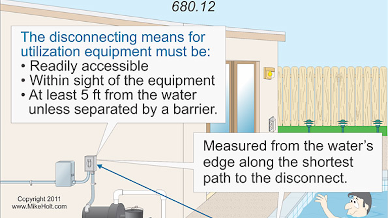
Stumped By The Code Requirements For Installing Maintenance
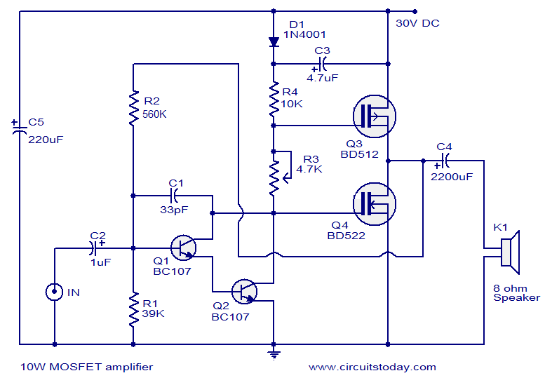
San ace 40 wiring diagram. 1 cooling systems fan instruction manual 1. We realized excellent cooling performance by leveraging our. Sanyo denki america inc. 40 20 276v 24v 12v 109p0424d601 40mm 109p0405j601 h speed f speed h speed g speed d speed d speed m speed m speed h speed f speed j speed dc fan 40mm. Wiring diagram 2001 ford taurus power windows hi this car is kicking everyone s ass. San ace 40 series.
San ace 40 general specifi. Ace motorhome wiring diagram. In the development phase we thoroughly reviewed impeller shape motor characteristics operating airflow and expected life to achieve target performance. The san ace 40 series dc fan provides efficient cooling for devices with high quality and high reliability overheating protection function. Thor motor coach wiring diagram. Safety precautions in order to ensure that this product is used safely be sure that you read and understand the following precautions fully and use the product only as directed.
General specifications motor protection systemcurrent cut system with reverse connection protection dielectric strength5060 hz 500 vac 1 minute between lead conductor and frame. B e sure to read these safety precautions carefully before installing connecting operating maintaining or inspecting this product. Sensor output pull up resistor 96v to 144v sensor circuit gnd0v brown yellow black. The san ace dc fans feature industry leading high airflow high static pressure low power consumption and low vibration. San ace cooling systems san ace is sanyo denkis brand name for cooling systems products such as cooling fans and cooling fan units. 2017 thor motor coach four.
Ace wiring diagram here you are at our site this is images about ace wiring diagram posted by benson fannie in ace category on oct 23 2019you can also find other images like images wiring diagram images parts diagram images replacement parts images electrical diagram images repair manuals images engine diagram images engine scheme images wiring harness images fuse box images. Wiring diagram rotating direction airflow directionrotating direction mounting hole mounting hole rotating direction airflow direction with sensor standard for fan power supply 45v to 55v sensor circuit gnd0v brown yellow black 276v max. If the fan blades are restricted an over current occurs and leads to a rise in the fan coil temperature. Thor ace 29 2 wiring diagram wiring diagrams pdf.


