Safety precautions in order to ensure that this product is used safely be sure that you read and understand the following precautions fully and use the product only as directed. Sensor output pull up resistor 96v to 144v sensor circuit gnd0v.
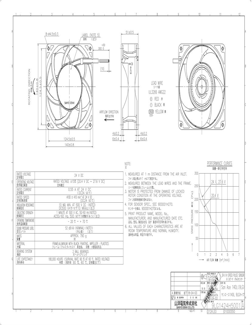
Sanyo Denki San Ace 140l Dc Fans Datasheets Mouser
San ace 60 wiring diagram. Ball bearing and wire leaded power connection. Clockwise direction of rotation viewed from front of fan blade and continuously run in a free air state. It reveals the parts of the circuit as streamlined shapes and also the power as well as signal connections in between the devices. San ace cooling systems san ace is sanyo denkis brand name for cooling systems products such as cooling fans and cooling fan units. Wiring diagram 2001 ford taurus power windows hi this car is kicking everyone s ass. Thor ace 29 2 wiring diagram wiring diagrams pdf.
Ul1007 24awg red and black yellow sensor brown control lead wire. C1097b001 201it dc dc fan 60 mm sq. This san ace 120 series 9gv type fan comes with plastic frame and impeller. Variety of trane ac wiring diagram. 372 05 10 0 20 50 30 40 10 15 005 010 0 015 020 0 10 20 30 40 50 inch h 2opa 静圧 風量 cfm m3min 50hz 100v115v200v230v 60hz 100v115v200v230v 109 150. Ace wiring diagram here you are at our site this is images about ace wiring diagram posted by benson fannie in ace category on oct 23 2019you can also find other images like images wiring diagram images parts diagram images replacement parts images electrical diagram images repair manuals images engine diagram images engine scheme images wiring harness images fuse box images.
B e sure to read these safety precautions carefully before installing connecting operating maintaining or inspecting this product. In the development phase we thoroughly reviewed impeller shape motor characteristics operating airflow and expected life to achieve target performance. 1 cooling systems fan instruction manual 1. The san ace dc fans feature industry leading high airflow high static pressure low power consumption and low vibration. Thor motor coach vegas 25 2 motor home class a for sale. Thor motor coach wiring diagram.
60 05 5003 4 ø4503 38 50 03 60 05 リード線 awg26 ul 1007 ul 1430型番9gv0612p1g03 のみ 回転方向 風吹出方向 50 300 0 取付用穴 297 5003 4 ø45 59 50 297 03 59 627 catalog no. We realized excellent cooling performance by leveraging our. 2017 thor motor coach four. Rotating direction airflow direction lead wire awg26 ul 1007 mounting hole. Ace motorhome wiring diagram. The 9gv1224p4g01 is a 24vdc 25mm thick axial fan with pwm speed control function and pulse sensors.
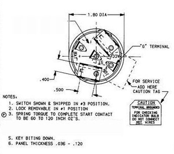
A wiring diagram is a simplified conventional photographic depiction of an electric circuit. Wiring diagram rotating direction airflow directionrotating direction mounting hole mounting hole rotating direction airflow direction with sensor standard for fan power supply 45v to 55v sensor circuit gnd0v brown yellow black 276v max.
