8 operating instructions movimot mmd with dtdv series ac motor 2 other applicable documentation safety notes 232 hoist applications movimot inverters are suitable for hoist applications to a limited degree only see sec. Start of desig nated operation is prohibited until it is determined that the machine meets the require.

Sew Eurodrive Dokumentationen Amp Software
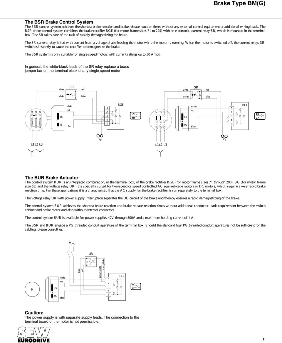
Sew movimot wiring diagram. Kw kg 73 50hz 60hz rmin bremse ka77 dt 90l4 bmg mm15 mlu 3009818304. The option is integrated in the movimot terminal box. Movimot can be equipped with a bem bes or urm brake control system as an option in conjunction with a modular terminal box. Sew eurodrive offers ready made eplan 550 macros for faster generation of wiring diagrams using caecad programs. Bem controls the standard brake bes controls the dc 24 v brake. Movimot inverters may not be used as a safety device in hoist applications.
Ac motors dr71 225 315 operating instructions. Additional function 9 see page 62. 2 detailed information about geared motor combinations can be found in the catalog movimot geared motors gear unit series2 04145bxx sew eurodrive typ nr. In case of installation in machines startup of movimot inverters ie. 99 1550hz v 380 500 v 380 500 221400 v 230 ma 665 iec 34 b3 099 350 350 54 f 6475 kl1 schmierstoff. Kw kg 73 50hz 60hz rmin bremse ka77 dt 90l4 bmg mm15 mlu 01001234560000 1550hz v 380 500 v 380 500 221400 v 230 ma 665 iec 34 b3 099 350 350 54 f 6475 kl1 schmierstoff bruchsal.
2safety notes designated use 8 compact operating instructions movimot mmd 24 designated use movimot inverters are components intended for installation in electrical systems or machines. 24 other applicable documentation. The sew eurodrive product range is displayed in an easy to use tree structure. Movimot mm03c mm3xc operating instructions 7 nameplates movimot type designations 3. Assortment of sew eurodrive motors wiring diagram. It shows the parts of the circuit as simplified forms and the power as well as signal links in between the devices.
A wiring diagram is a simplified standard pictorial representation of an electrical circuit. 31 wiring diagram mlu11a mlu21a option 32 wiring diagram mlg11a mlg21a option 03272bxx 03182bxx 1 observe enable direction of rotation see the section connection of movimot basic unit functions of terminals cwstop ccwstop with control via rs 485 interface 13 14 15 l1 l2 l3 r l f1f2 k1a k1b rs rs l1 l2 24v mlua movimot 24v. Gear units r7 f7 k7 s7 series spiroplan w operating instructions cm synchronous servomotors. The macros enable the user to create a standard layout adapted to the typical eplan functions.
