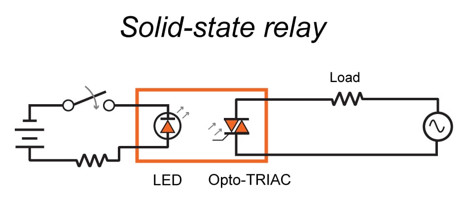
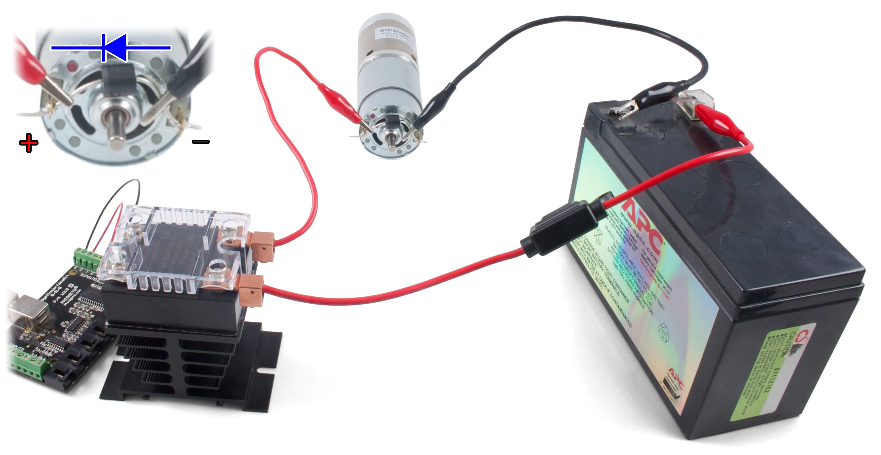
Solid state relays ssrs turn on or off the power being supplied to other devices in a similar fashion as a physical switch. Connect l positive terminal to the positive terminal on battery 2.
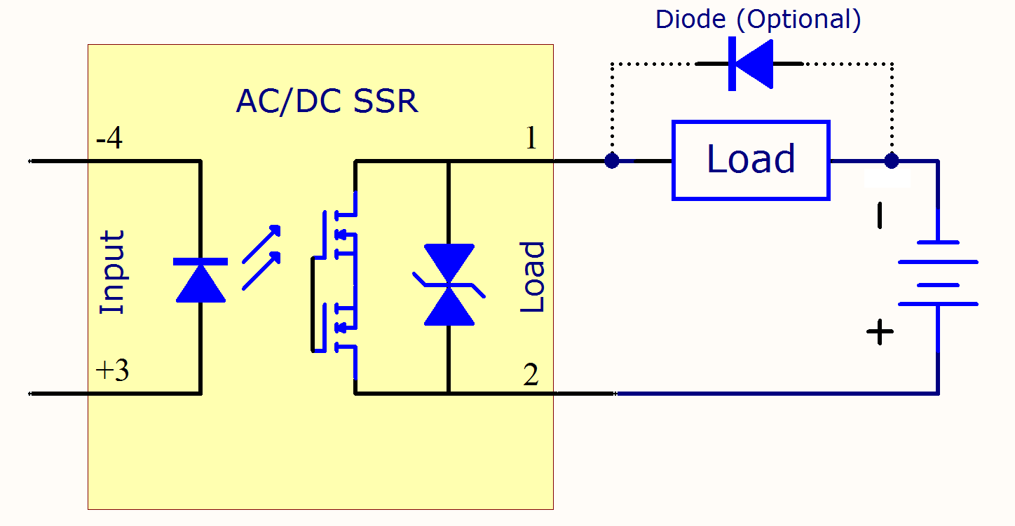
Solid State Relay Primer Phidgets Support
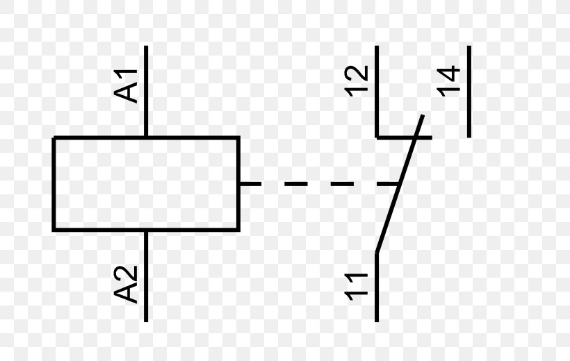
Solid state relay wiring diagram. Each channel is capable of handling 50 amps for up to 8 seconds or 20 amps of continuous current. Connect r negative terminal to the negative terminal on battery 1. This solid state relay also features built in over current protection and heat sink. Dayton solid state relay wiring diagram. Two circuit diagrams showing the improper and proper ways of switching mains electricity with a relay. A wiring diagram is a simplified traditional pictorial depiction of an electrical circuit.
Response time between this solid state relay and a mechanical relay. Variety of solid state relay wiring diagram. Solid state relay dcdc. The simplest approach to read a home wiring diagram is to begin at the source or the major power supply. It reveals the elements of the circuit as streamlined shapes as well as the power and also signal links in between the gadgets. The wiring diagram on the opposite hand is particularly beneficial to an outside electrician.
Sometimes wiring diagram may also refer to the architectural wiring program. Connect r positive terminal to the push button switch. Your load will probably be inductive if it is built around a large coil of wire motors and transformers. The operation of ssr solid state relay and emr electromagnetic relay or contact relay is same while the main different between ssr and emr is that there are no mechanical parts and contacts in ssr relay. Hybrid solid state relay ssr circuit diagram a solid state relay ssr is an on off control device in which the load current is conducted by one or more continue reading. This module takes the place of 4 standard relays and eliminates unsightly wiring.
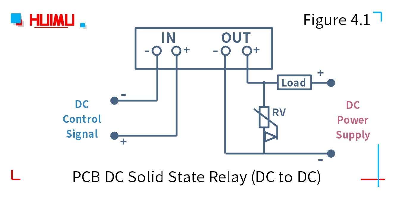
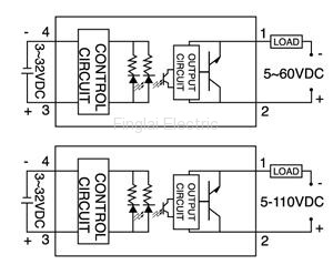
Assortment of solid state timer wiring diagram. Please note that the diagram refers to dcdc type solid state relay ssr. Overload protection occurs at 80 amps. It shows the parts of the circuit as streamlined forms as well as the power as well as signal connections between the devices. With 4 channels providing up to 200 amps of momentary or 80 amps constant combined power. Clean up your wiring with an msd solid state relay block.
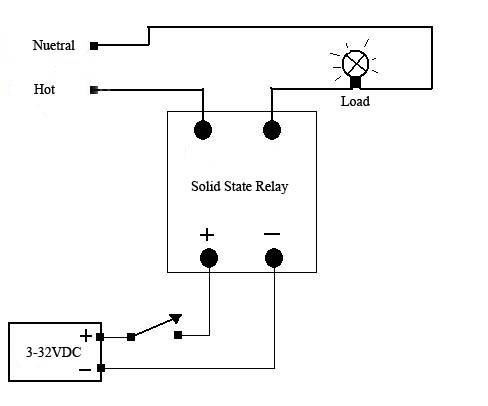
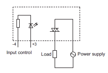
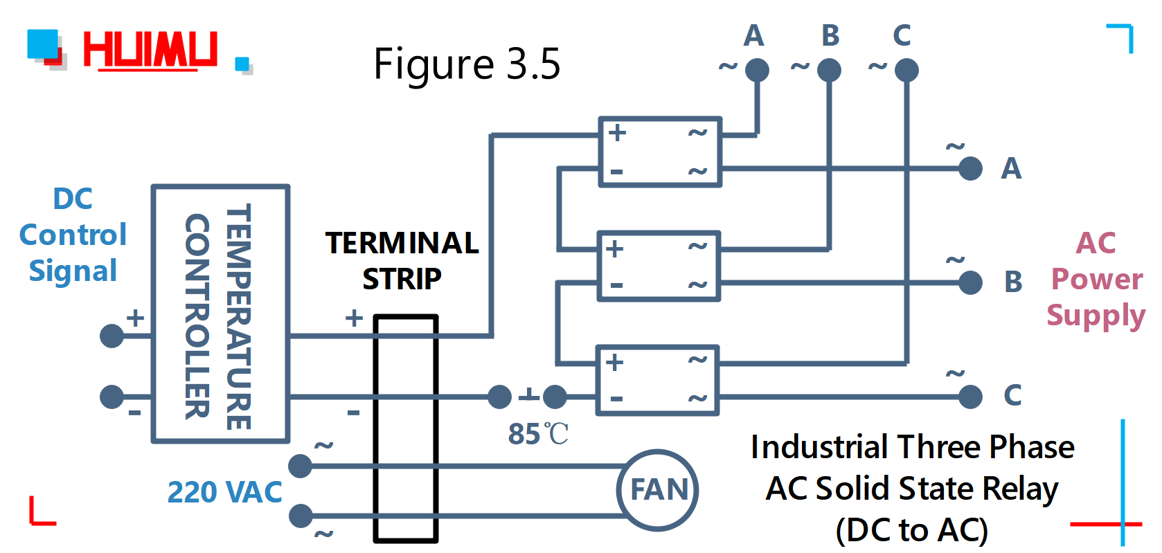
Before installation and use please confirm whether the specifications such as input current input voltage output current output voltage and etc. This relay is rated at 20 amp continuous and can be used at higher current loads for short periods of time drag racing etc. 4 independent channels can be activated using either power or ground. A wiring diagram is a streamlined conventional pictorial depiction of an electric circuit. The diagram below shows how to wire a solid state relay. The circuit wiring diagram of the industrial random conduction dc to ac solid state relay or industrial random fire dc to ac ssr is the same as the zero crossing dc to ac solid state relay.
