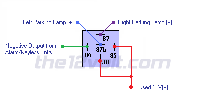
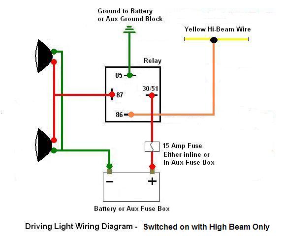
At the moment it is wired up as you would for a positive switching vehicle the same as in my 07 td rodeobut the only way to turn the driving lights off is via the switch on the dash. Convert a negative output to a positive output relay wiring diagram.

How To Wire A Relay For Off Road Led Lights Extreme Lights
Spotlight wiring diagram negative switching. Positive of the second led connected to the cathode negative of the first. To wire a series circuit like the one shown the positive output from the driver connects to the positive of the first led and from that led a connection is made from the negative to the positive. To check for negative switchingconnect the test light to a positive power supply and check for a wire that only has an earth when high beam is switched on. It shows the parts of the circuit as simplified forms and the power and also signal links between the gadgets. Drill holes to mount the spotlight and light switch in your preferred locations. Switching power supplies.
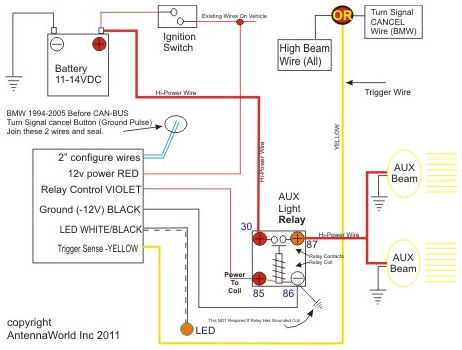
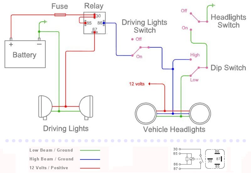
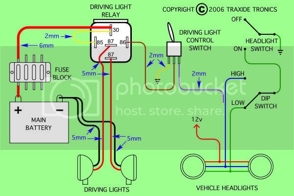
Assortment of 12v relay wiring diagram spotlights. The fifth wire should connect the last open post on the relay to the switch. I was thinking maybe the trigger wire for the spotties and lights etc needs to be joined actually in the h4 switching harness rather then the factory wiring. Hi ive been searching for a clear diagram explanation of how to wire up a driving light relay properly on a toyota rav 4 which uses negative switching. If you want the extra control of switching your spot lights off when the high beams are switched on for instance when the spotlights are covered an extra switch can be connected in the relays earth wire. All the ones i do have the h4 switching harness which works fine unless you have spotlights or light bars already fitted except for the hig beam light.
Wiring diagram for spot lights on a hilux. One thing i would change is the cable between the battery and the fuse block this should be at least 6mm to give the best results. It a basic headlight wiring up grade and you dont need to know whether the vehicle is positive or negative switched the wiring sorts it out automatically. Then run a fourth wire from the relay to the positive post of the spotlight and solder in place. A wiring diagram is a streamlined conventional pictorial depiction of an electrical circuit. The image to the right shows an example.
A possible idea is to earth the wires onto the negative pole of the battery. To ground and power the light switch run one wire from a switch prong to a bolt on the. Its always safest to disconnect running power by removing the negative terminal from the battery for the easiest installation. Once this has been established refer to the relevant wiring diagram. Run the switch through to the inside of the vehicles cabin via a pre existing rubber grommet in the firewall. If you have a switch or an alarm or keyless entry that has a negative output that you wish to use to switch a device that requires 12v such as a horn dome light parking lights head lights hatch release etc wire a relay as shown below to convert the negative output trigger to a positive output.

