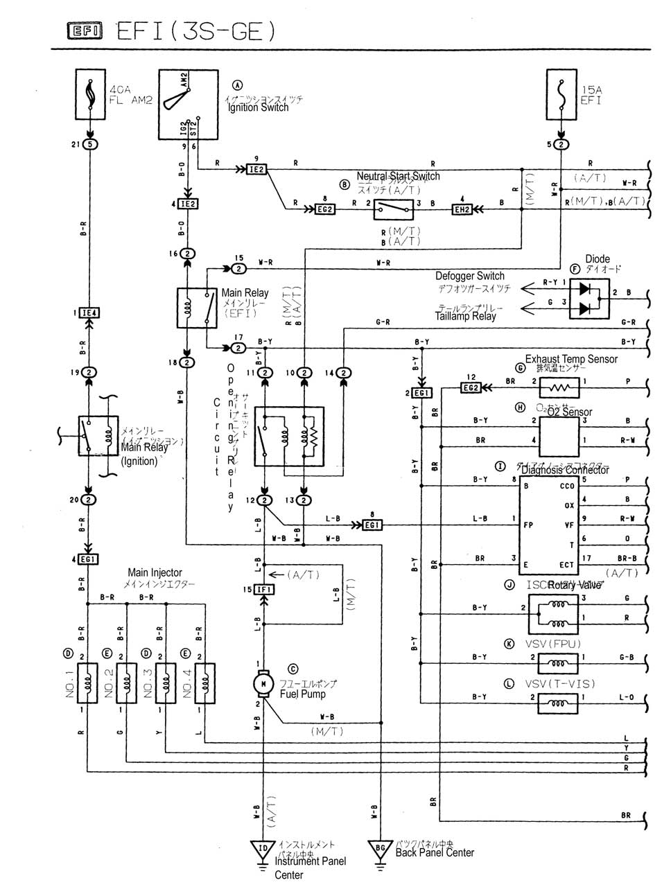
Sxe10 3s ge engine control ecu pin configuration inspection item terminal terminal no input output. Sxe10 3sge wiring diagram3s fe repair manual pdf.

Toyota Altezza Altezza Gitasxe10 Aeavf Electrical Wiring
Sxe10 3sge wiring diagram. For the parameter setting for the airflow meter process and wiring modification refer to page 3sxe10 startdata was prepared based on a vehicle equipped with the factory airflow meter. Sxe10 3s ge summary engine control electrical wiring diagram. This is the wiring diagram which i found most helpful these are the 2 ecu connectors which connect to the rest of the vehicle all the circuits on the other 3 go to the engine. 1990 jdm 3sge ecu pinoutswiring diagrams mr2 australia genuine jdm low mileage used 1998 2005 toyota altezza rs200 beams 3sge 20l dual vvti engine with rwd 6 speed manual transmission sxe10 3s ge engine control diagnosis. The letter in the circle under the connector diagram corresponds to the connector letter in the wiring diagram above just below that is the connector shell part number. 3sge beams ecu pinout.
Engine control electrical wiring diagram sxe10 3s ge engine control ecu pin configuration foreword wwwjosvandijkennl information on the electrical system of the 1994 toyota camry applicable models. 3sge 3sgte up to gen 3. Unfortunately the link was to a 3rd party website which the loc have no control over if you google 3s ge pinout ot wiring diagram there are many links which should help you. Rs200 sxe10 3sge 3s engine manual toyota altezza 3sge beams j160. Any help would be greatly appreciated. Manual 3s toyota ebook download as pdf file pdf or read book online.
Doing a elite 1500 install but i need the wiring diagram to combine with existing harness. Use rpmpressure and input a 05v signal to suit. Find solutions to your ecu wiring diagram 3sfe question. Wiring diagram ecu 2kd ftv. Urgent need of altezza 3sge wiring diagrams practical harness construction club level. I need some help getting a hold of wiring diagrams for this sxe10 altezza rhd.
Uploaded 3sfe 3sge wiring diagrams. Sxv10 series mcv10 series the actual. Inserted diagram is corrected output waveform 1 pulse occurs on each 30ca. Twist wire l p p b r lg br w sealed wire twist wire r r o2 sensor no1 sealed wire r w r w b r w w g g br b sealed wire o2 sensor no2 twist wire r sealed wire w sealed wire g r g od direct clutch speed sensor b w l l crank position twist wire y r y r l sensor sealed wire r l r l at speed sensor w r w r g g cam position sensor. For the vehicle without the airflow meter edit the parameter shown in the diagram on the right.


.gif)


.gif)


