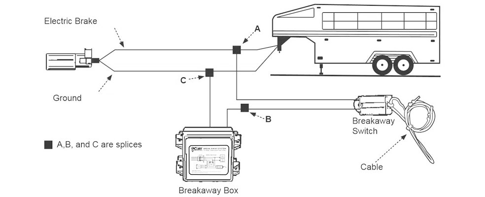
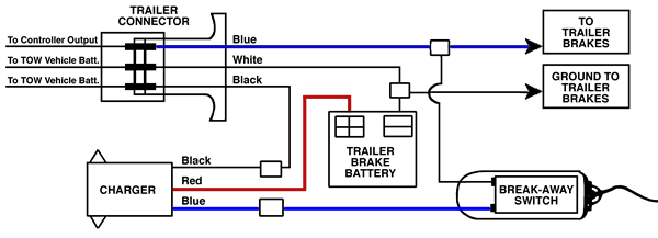
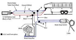
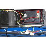
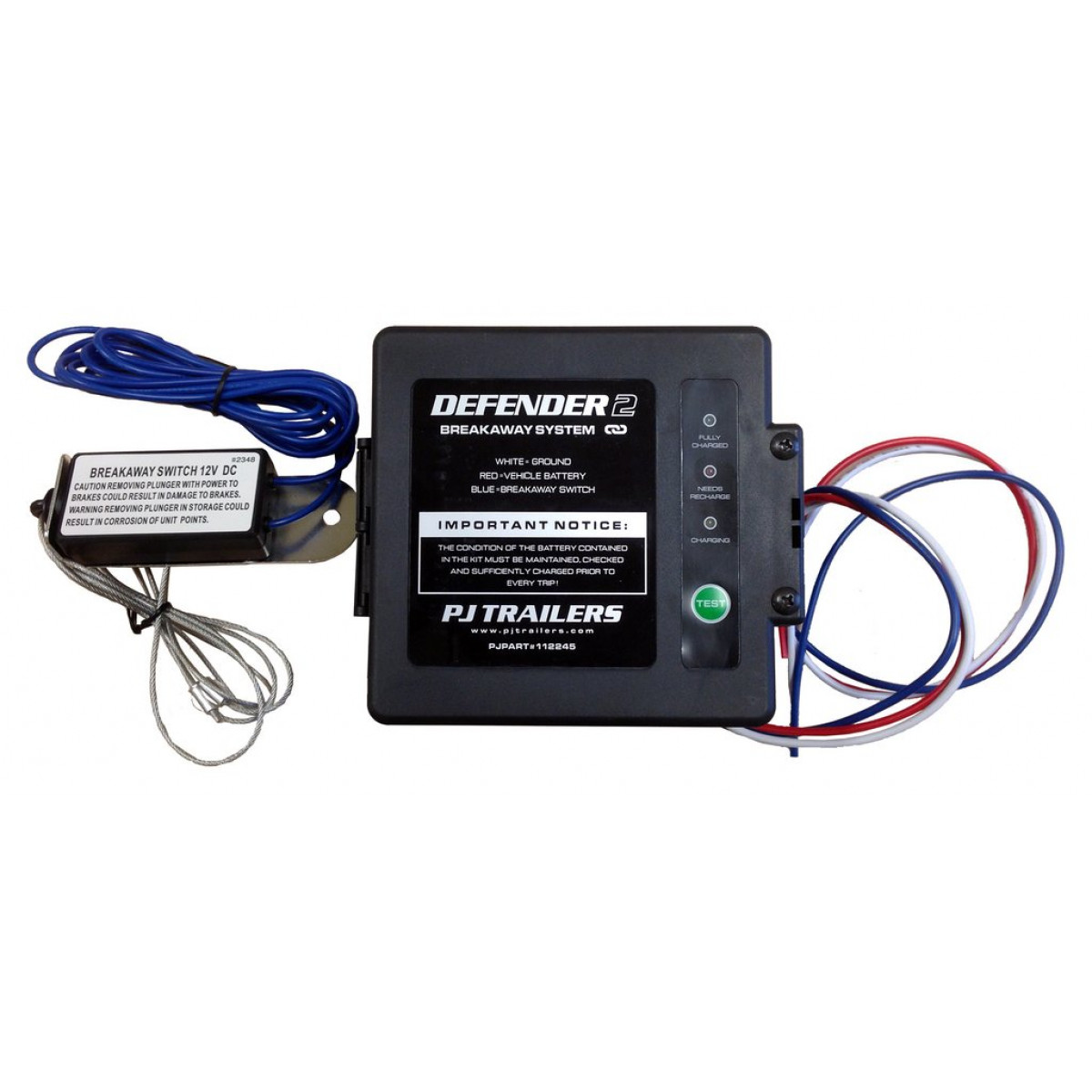
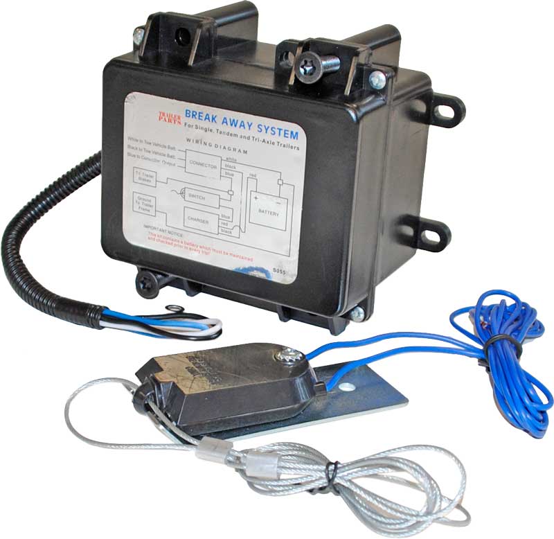
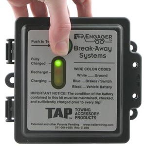
The following diagram shows a typical wiring configuration for a hopkins breakaway kit with a battery charger. Connect other blue wire of break away switch to the blue wire labeled brake from the break away box b.

20400 Tap C Engager Break Away Kit With Led Test Light Front Mount
Tap breakaway system wiring diagram. See wiring diagrams on reverse side your trailer must have operational electrical brakes andyour auxiliary power wire on the tow vehicle must be connected to use this product. Break away system for single and tandem trailers break away box. A wiring diagram is a simplified conventional photographic depiction of an electric circuit. Hopkins breakaway kits with built in chargers require four connections. Some other manufacturers have similar configurations but not all wire colors are the same. The engager breakaway system wiring diagram new wiring diagram for trailer breakaway kit and redline trailer of the engager breakaway system wiring diagram wiring diagram for electric brakes on a trailer new stock refrence lovely of example full we collect lots of pictures about tap breakaway kit wiring diagram and finally we upload it on our.
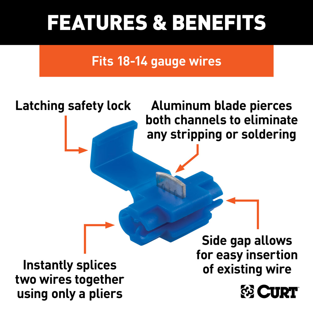
Some break away systems do not have a black wire. Splice one blue wire of the break away switch to the electric brake wire coming from the trailer side connector a see diagram on next page. Variety of trailer breakaway wiring schematic. These systems will require the battery be fully charged by a trickle charger before use. One connection has already been made inside the battery box. It shows the components of the circuit as streamlined shapes and the power and also signal connections in between the devices.
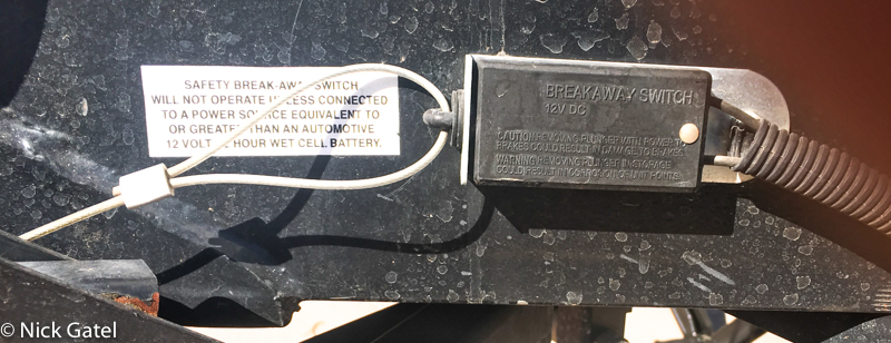
Break away switch with cable 20099 20100 or self tap screws 20400 20401 3 with 20099 4 with 20400. Wiring diagram on back cable installation fig 1 fig 2 fig 3 cable cable cable break away switch break away switch break away switch bumper clevis safety chain pocket pin break away. Vehicle is in use.
