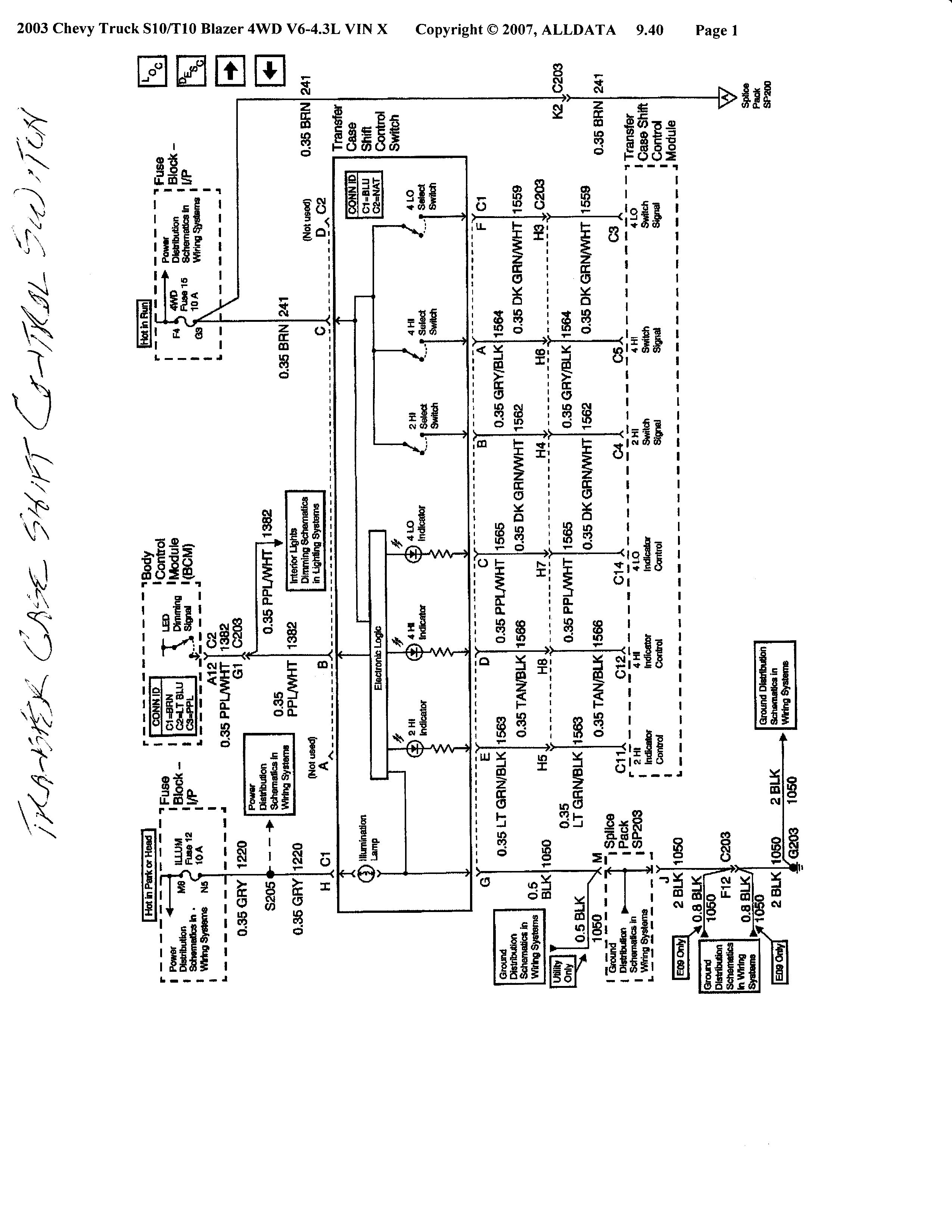
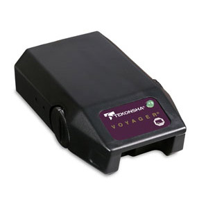
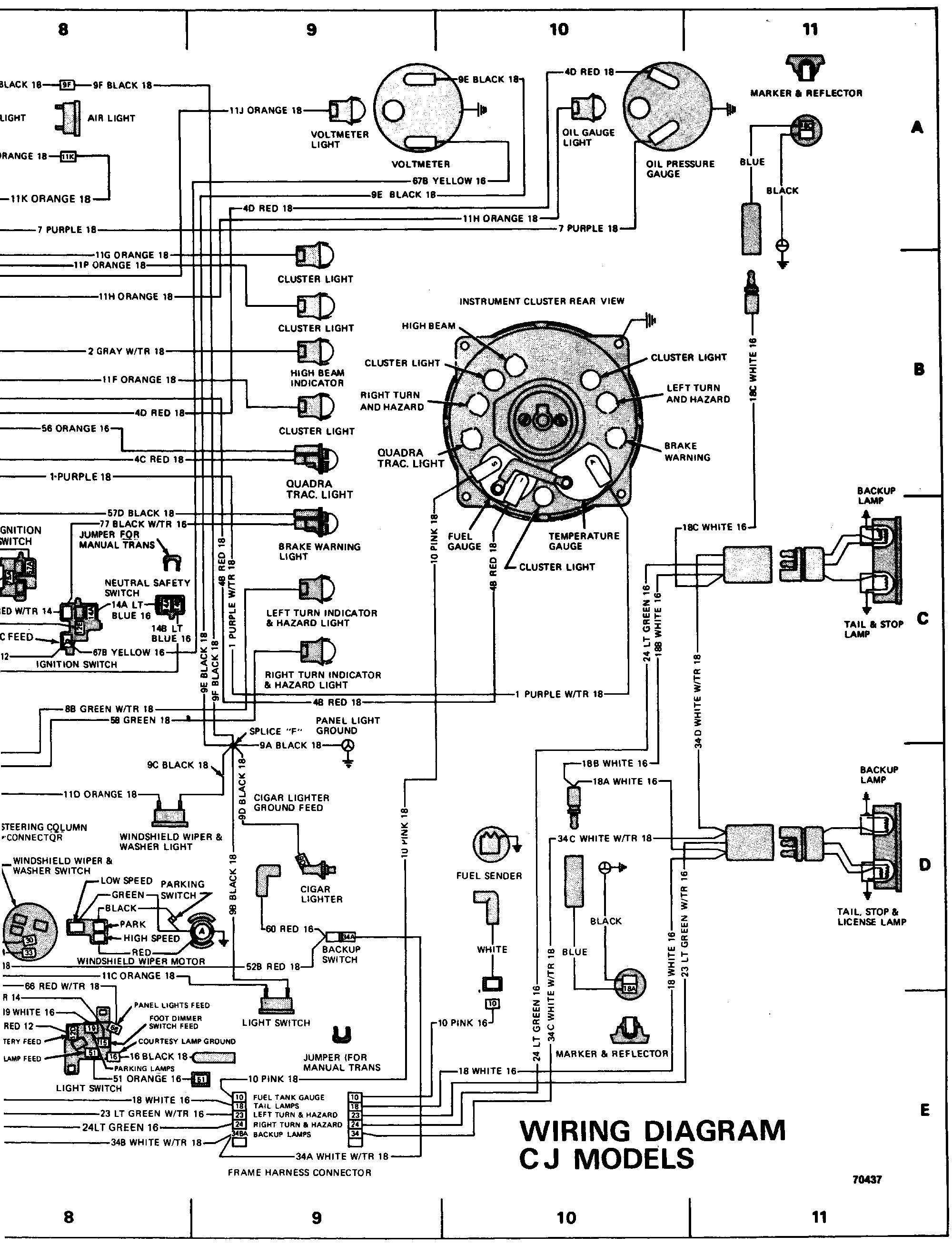
Tekonsha voyager wiring diagram tekonsha voyager electric brake controller wiring diagram tekonsha voyager installation instructions tekonsha voyager wiring diagram every electric structure is made up of various distinct components. It shows the parts of the circuit as simplified shapes and the power and signal links in between the gadgets.
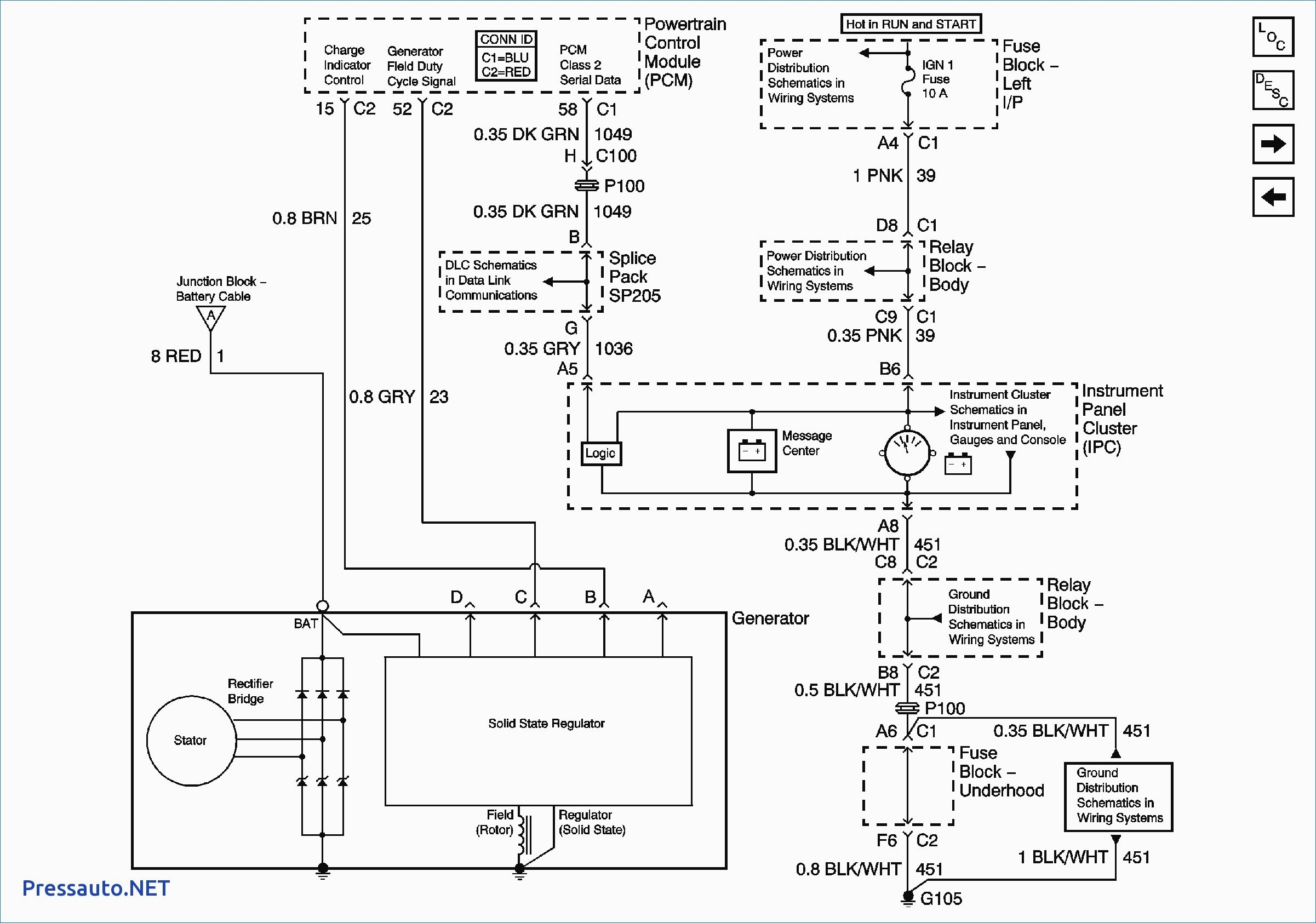
B51e4a3 Tekonsha Primus Iq Wiring Diagram Wiring Library
Tekonsha voyager xp wiring diagram. Tekonsha voyager wiring diagram you will need a comprehensive skilled and easy to understand wiring diagram. The problem i have is there are 5 wires on the wiring harness and only 4 on the controller. Assortment of tekonsha voyager wiring diagram. A wiring diagram is a streamlined standard pictorial depiction of an electrical circuit. Warning the brake control must be mount ed from 20 degrees nose down to 70 degrees nose up. See below failure to install brake control within these constraints may cause your control to become inoperable.
I have included the instructions for the voyager an faq article that features a basic diagram near the middle of the document and an article on wiring a brake controller from scratch. Depending on your vehicle year make and model i will be able to provide instructions for wiring the tekonsha voyager brake controller. 6 x 38 screws. With this kind of an illustrative manual you will have the ability to troubleshoot prevent and full your projects without difficulty. Otherwise the structure wont function as it should be. I have a 2006 chevy suburban equipted w a trailer package i have the wiring harness to install on to my tekonsha voyager brake controller.
Each part should be set and connected with other parts in particular way.
