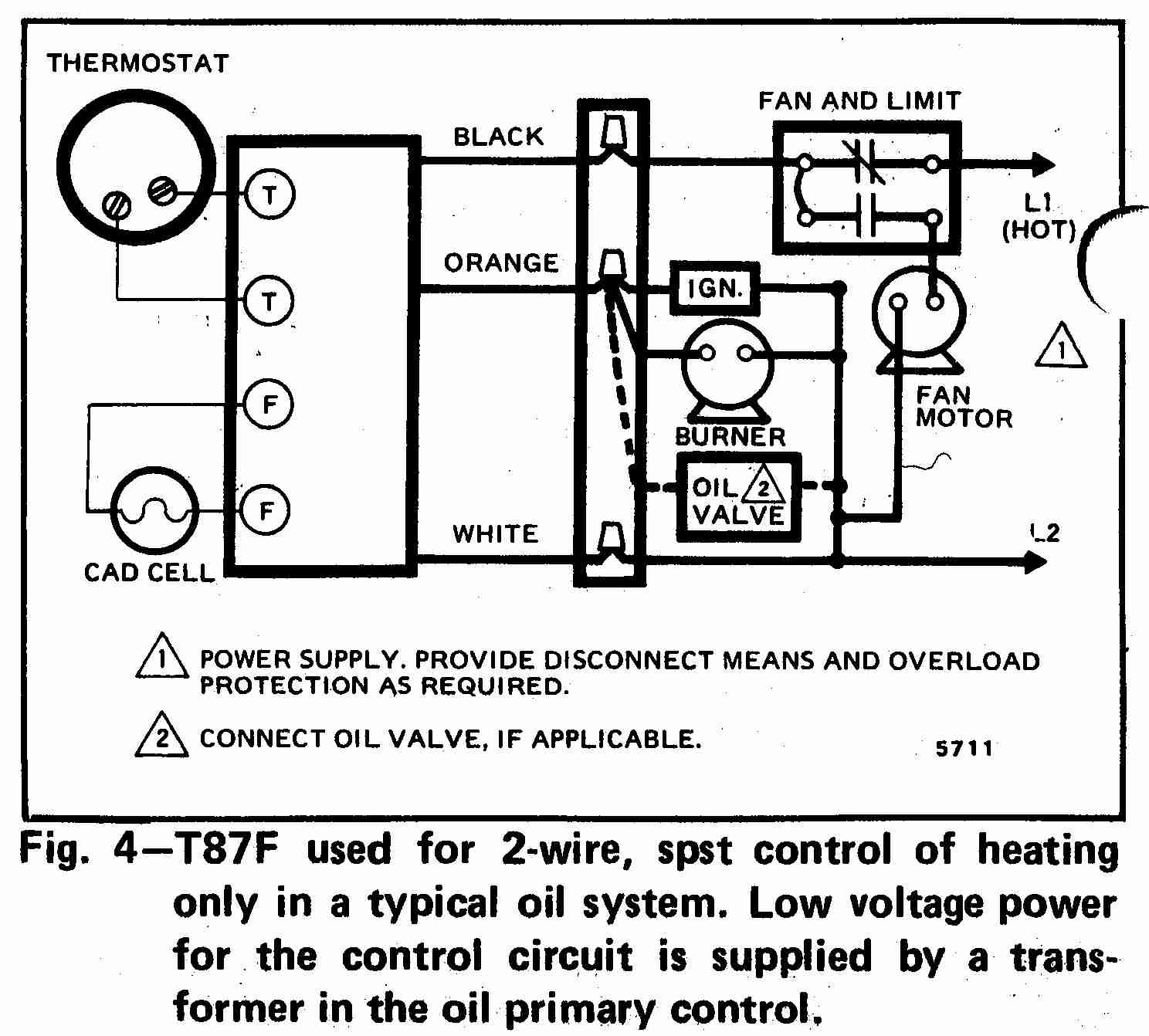
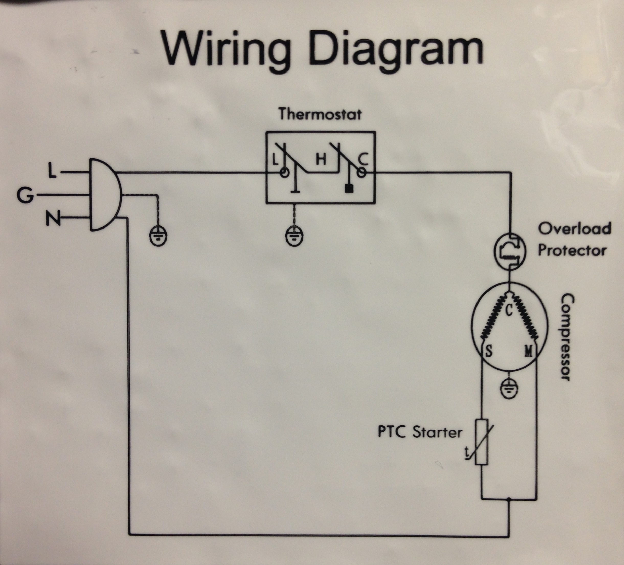
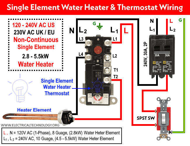
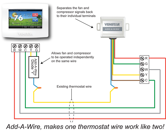
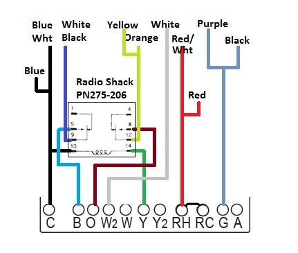
The table above provides a more complete list of honeywell thermostat wiring colors and their uses. A wiring diagram is a streamlined conventional pictorial representation of an electrical circuit.

Carrier Programmable Thermostat Wiring Diagram Carrier Air
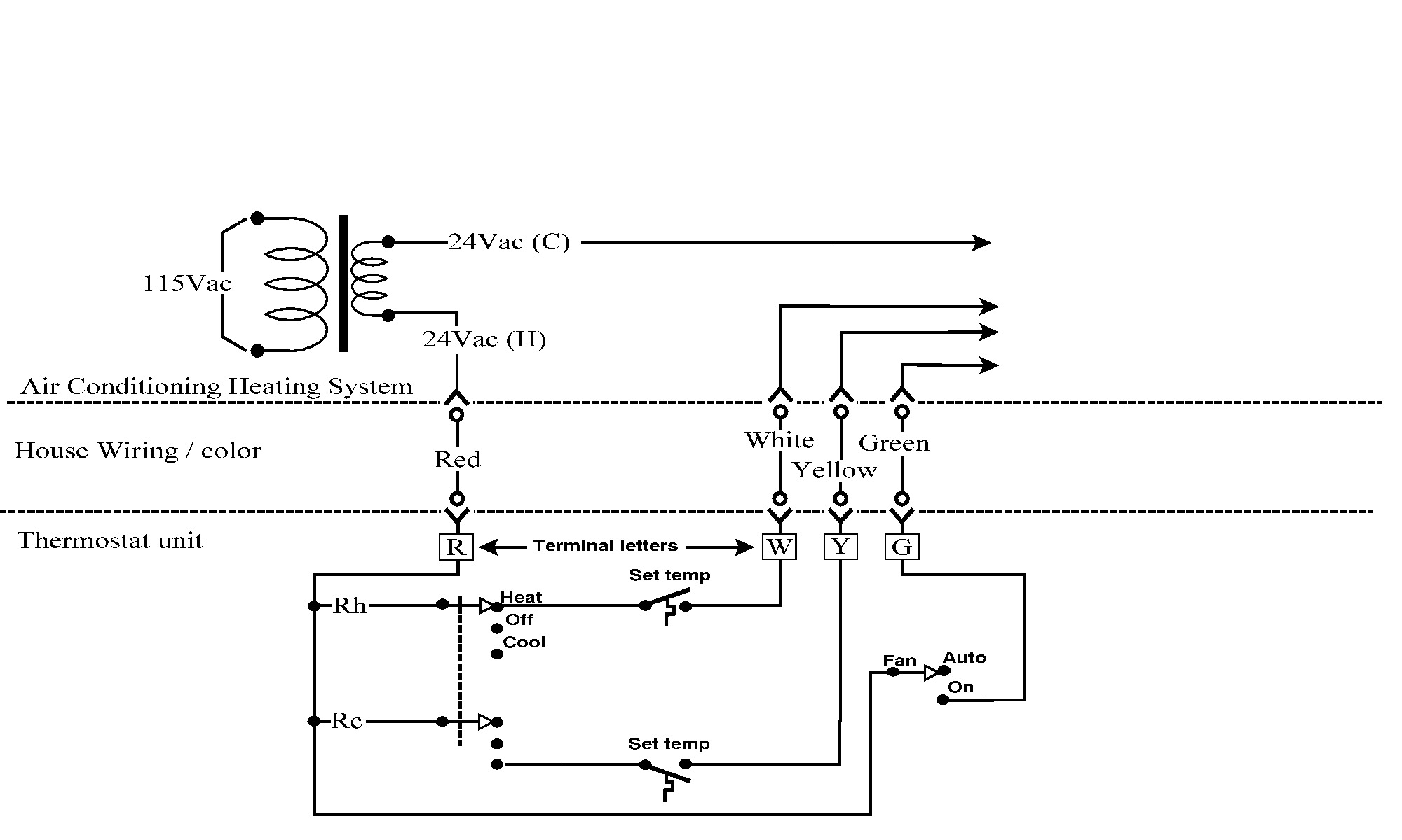
Thermostat wiring diagram. Red now there can be two separate wires for this. Smart thermostats wifi. It is a red wire and comes from the transformer usually located in the air handler for split systems but you may find the transformer in the condensing unit. Thermostat wiring diagrams thermostat wiring colors and terminals. The thermostat is the control device that provides a simple user interface with the internal workings of your homes climate control system. Thermostatic wiring principles by bob scaringe phd pe.
In fact the wiring of a thermostat is quite simple circuitry the confusion arises principally because. Green the green wire connects to the fan. Thermostat wiring and wire color chart thermostat wiring colors code. But here is a list of the most common wire color mappings as seen in many four wire t stat setups. Honeywell thermostat wiring diagram 4 wire examples. Variety of 4 wire thermostat wiring diagram.
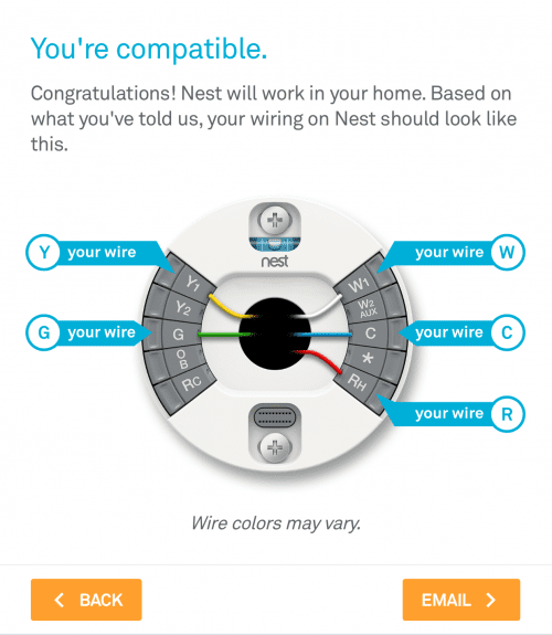
White the white wire is what connects to the auxiliary heat on your system. C 24 vac common you might see blue purple or brown typically used for this wire. The basic heat ac system thermostat typically utilizes only 5 terminals. Many technicians have great difficulty understanding how to properly wire a thermostat or how to replace a thermostat with a different thermostat. By the use of an adjustable set point the job of the thermostat is to turn on either the heating or cooling system to maintain the desired room temperature in the home and to turn off the system when the desired temperature is achieved. Orange this wire connects to your heat pump if you have one.
White rodgers shows a slightly different type of wiring diagram that mirrors a ladder logic. Color of wire and termination. Rc red wire power 24 vac rh or 4 red wire jumpered power 24 vac w white wire for heating enable y yellow wire for cooling enable. The diagram below shows how a basic 4 wire thermostat is connected as indicated by the color code chart above. It reveals the parts of the circuit as streamlined shapes and the power and also signal connections in between the gadgets. Yellow the yellow wire connects to your compressor.
R the r terminal is the power. Heating only thermostat wiring diagrams if you only have a furnace such as a gas. Basic thermostat types.


