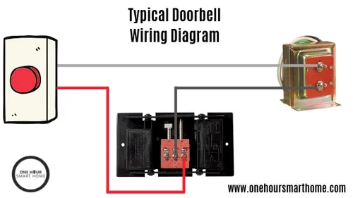
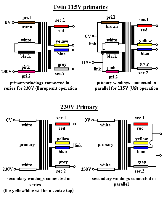
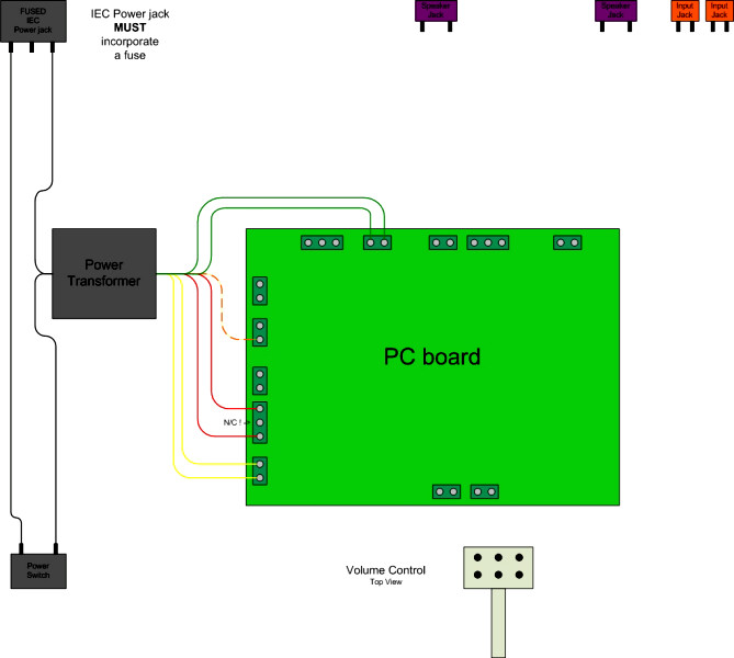
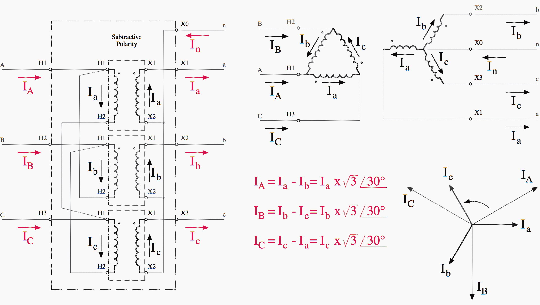
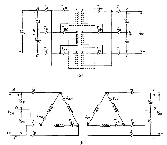
It shows the parts of the circuit as simplified forms and also the power and signal connections in between the tools. Variety of electrical transformer wiring diagram.
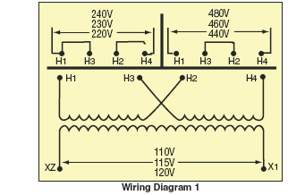
Industrial Control Transformers
Transformer wiring diagram. 3 shows this same isolated transformer connected as a stepdown autotransformer while fig. Transformer to wiring imageresizertool com november 23rd to transformer wiring diagram as well asgeneral electrical connection diagramsacme transformer wiring diagrams primary. A beginner s guide to circuit diagrams. A first take a look at a circuit diagram may be complicated but if you can. Generalgeneralelectrical connection diagramsacmetransformerwiring diagrams. Variety of control transformer wiring diagram.
Click on the image to enlarge and then save it to your computer by right. 2 5 bnfc x1 h1 x2 x3 h2 h3 x0 3 2 1 3 2 1 3 2 1 connect connect primary primary inter secondary volts lines to connect lines to 240 h1 h2 h3 1 228 h1 h2 h3 2 216 h1 h2 h3 3 secondary volts 208 x1 x2 x3 120. X4x1 h4 h3 h2 h1 x2x3. A transformer can not act as a phase changing device and change single phase into three phase or three phase into single phase. 12 2 2 anfc 4 2 12 bnfc x4 x1 h10 h2 h3 h1 x2 x3 h5 h6 h4 h7 h8 h9 connect. 240 x 480 secondary.
A wiring diagram is a streamlined traditional photographic depiction of an electric circuit. None x4x1 h4 h3h2 h1 x2 x3 primary. General electrical connection diagramsacme transformer wiring diagrams primary. Figure 4 wyewye transformer connections diagram click to expand diagram one problem inherent to wyewye transformers is the propagation of third harmonic currents and voltages. 2 is a wiring diagram of an isolated transformer including the input and output voltage at each winding. Control transformer wiring diagram download.
4 shows it connected as a bucking autotransformer. 240 x 480 secondary. V l is the line to line voltage and v p is the phase to neutral voltage. These harmonics can cause interference in nearby communication circuits as well as other assorted power quality problems. 120240 2 212 anfc 4 2 2 bnfc. Wiring diagram book a1 15 b1 b2 16 18 b3 a2 b1 b3 15 supply voltage 16 18 l m h 2 levels b2 l1 f u 1 460 v f u 2 l2 l3 gnd h1 h3 h2 h4 f u 3 x1a f u 4 f u 5 x2a r power on optional x1 x2115 v 230 v h1 h3 h2 h4 optional connection electrostatically shielded transformer f u 6 off on m l1 l2 1 2 stop ol m start 3 start start fiber optic.
To make the transformer connections compatible with three phase supplies we need to connect them together in a particular way to form a three phase transformer configuration. Variable transformers schematics wiring diagrams. 240 volts delta secondary.


