Determine if the electric heaterunit is field flippable between left and right handing. Dtfs f dtfs dtqs dtqp dfls dflp dpfc dlhk.

Ac 7800 Diagram Air Handling Unit Schematic Air Side
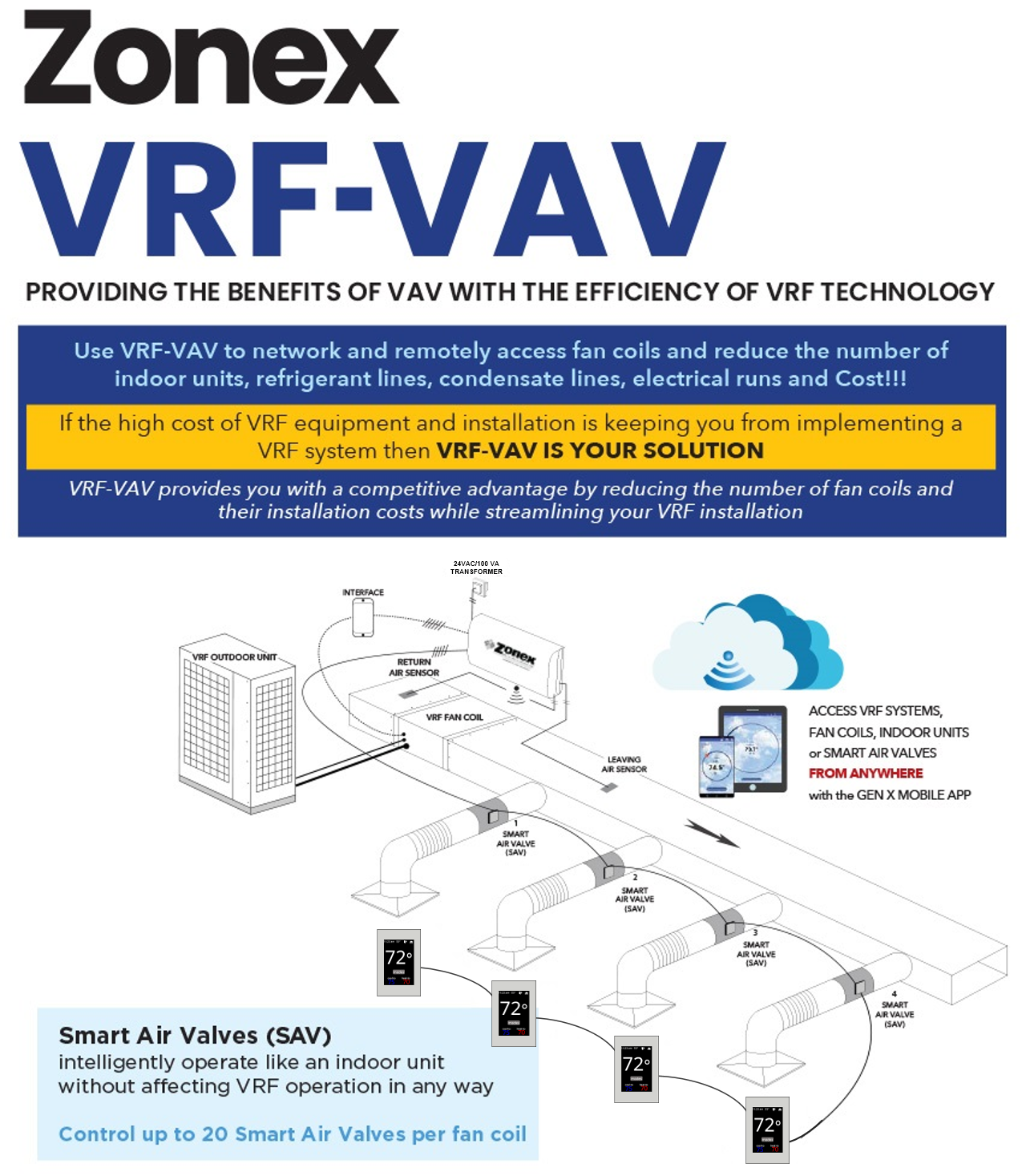
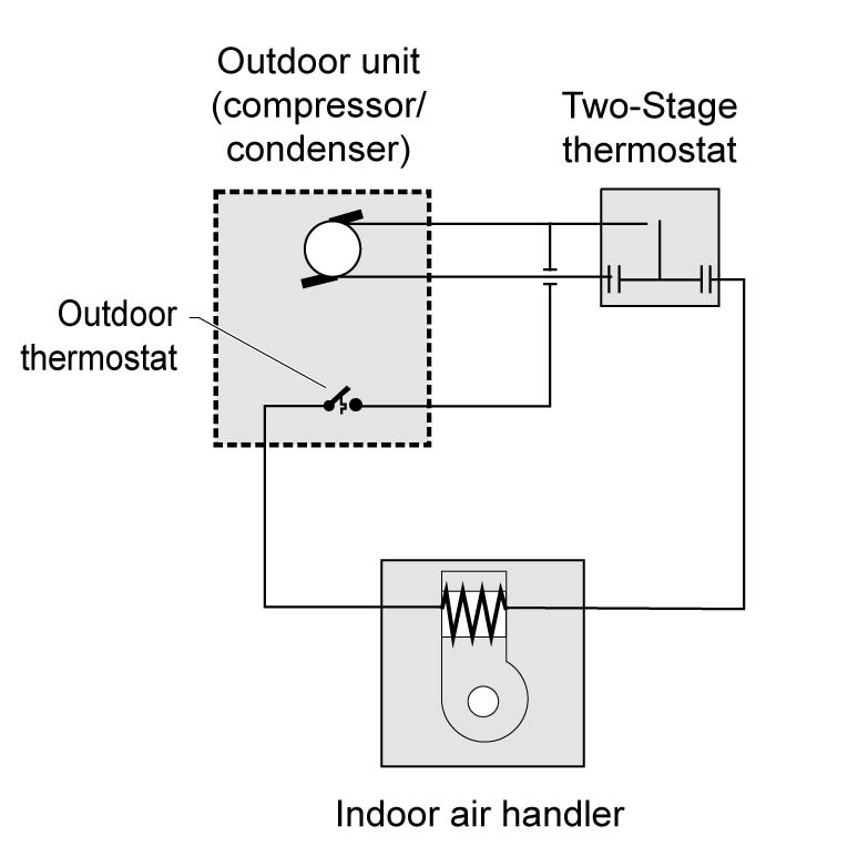
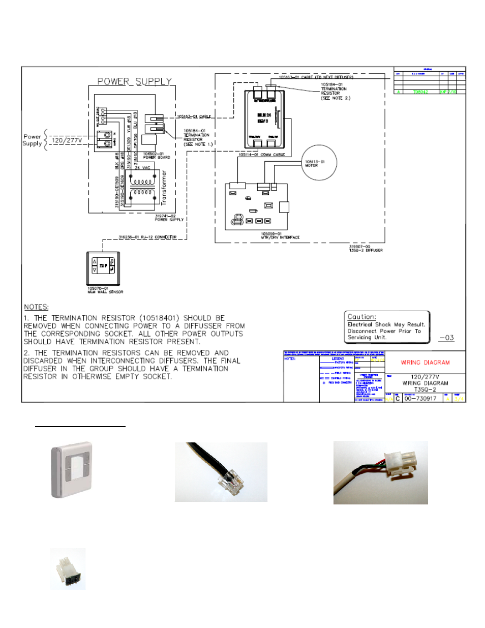
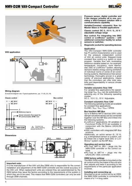
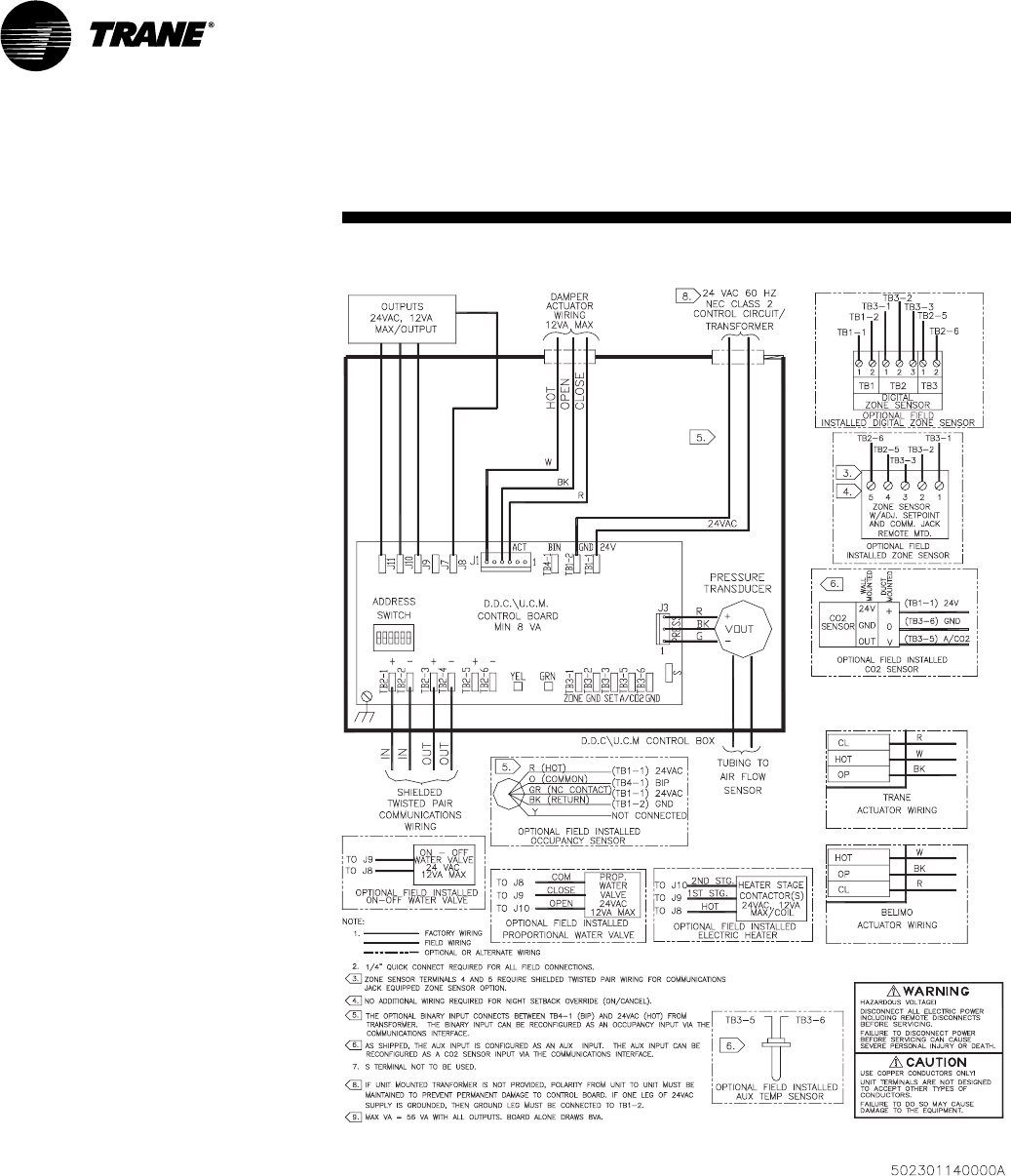
Vav wiring diagram. 2 vav controllervariable air volume vav controller wiring details page 25 power source and loads 26 grounding and isolation 27 io and communication terminals 29 power zone bus and n2 connections 36 analog inputs 36 binary inputs 38 binary outputs 38 analog outputs 38 zone bus 39 wiring to rly50002 relays 39. Alerton vav sd2a controller honeywell mlb 6161 actuator. When this controller is factory installed on trane variable air volume vav terminal units the factory downloads the unit with the appropriate vav programs and configuration settings for the. Variable volume air terminal unit control diagram no supplemental heating with supplemental heating air flow cfm room temperature f heating minimum vav box control sequence sp tu rhc hws hwr v 1 reheat coil air terminal unit air flow te atu controller pc te tu rhc hws hwr v 1 reheat coil air terminal unit air flow te atu controller pc te. If the unit is an sdv or fdca2 and the element terminal cutout in the bottom of the. Before wiring your electric coil review and adhere to all local building codes ordinances and the national electric code pertaining to installation of equipment.
Mounting and wiring variable air volume modular assembly vma 1400 series controllers technical bulletin 3 mounting and wiring vma1400 series controllers introduction the integrated vma14101420 which includes a controller actuator and pressure sensor mounts on the variable air volume vav terminal box. Alerton vav sd2a controller honeywell mlb 6161 actuator. The vma1430 mounts anywhere on the. Reduced the number of wiring diagrams to two which show typical trane factory wiring. With ecm motor manual pwm. Alerton vav sd2a controller honeywell mlb 6161 actuator.

