The supply for this can be taken from most existing circuits providing the switched fused unit sfu is present at the start of the installation and appropriately fused to protect the sub circuit cabling and accessories. Take a closer look at a ceiling fan wiring diagram.
Wiring Vortice Fan Diynot Forums
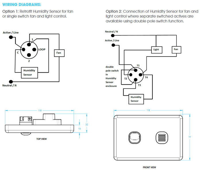
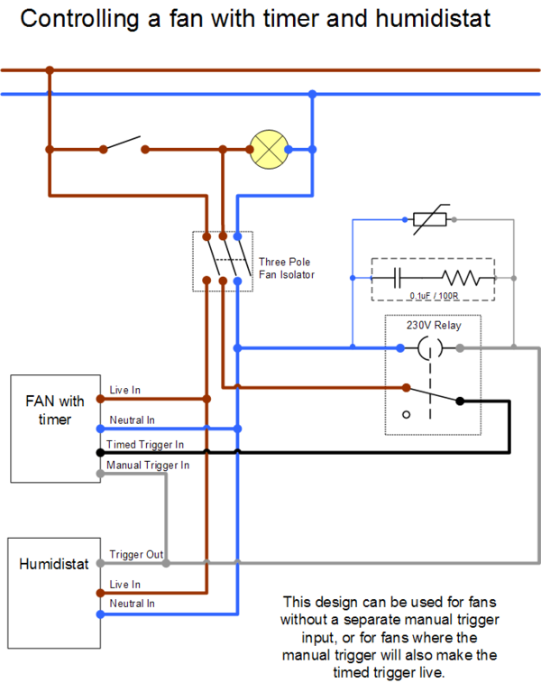
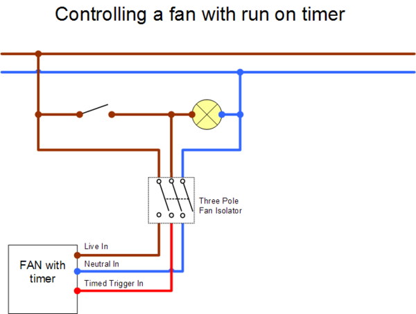
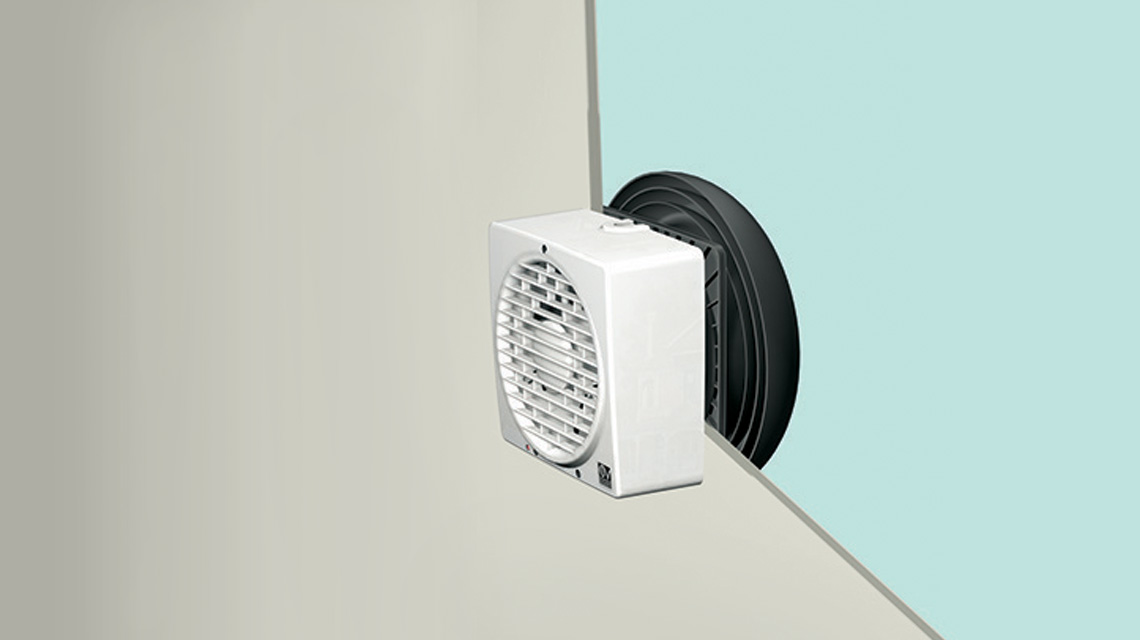
Vortice fan wiring diagram. The source is at the switches and the input of each is spliced to the black source wire with a wire nut. With these diagrams below it will take the guess work out. Model designed for windowwall mounted installation. Ceiling fan wiring diagram. Diagram showing wiring method for an independently switched extractor fan. This might seem intimidating but it does not have to be.
Wiring diagrams a fan terminal block b isolation switch double pole c 2 way switch a fan terminal block b isolation switch double pole ca v0 ca v0 d ca we d ln ln a b nl b c a max min n1 l2 3 vortice hoods microrapid v0 thermologika microsol v0 tiracamino ca wall ca roof new vortice hoods vortex hoods a fan. This wiring diagram illustrates the connections for a ceiling fan and light with two switches a speed controller for the fan and a dimmer for the lights. Pick the diagram that is most like the scenario you are in and see if you can wire up your fan. Wiring diagrams s6 wiring wiring diagrams diagrams vort press vort press i a fan terminal block b isolation switch double pole c speed selector switch ca v0 serie ca ca v0 d vmc ariant a b l n l n a fan terminal block b isolation switch double pole vortice hoods microrapid v0 thermologika microsol v0 tiracamino ca wall ca roof a fan terminal block b. From the switches 3 wire cable runs to the ceiling outlet box. Installing the switched fan.
Prevents the entry of cold air and bad smells when the appliance is switched off. Reversibility function intake or extraction.

