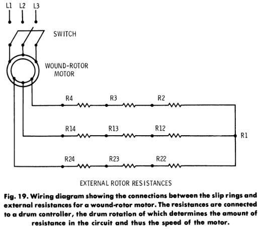
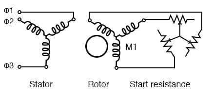
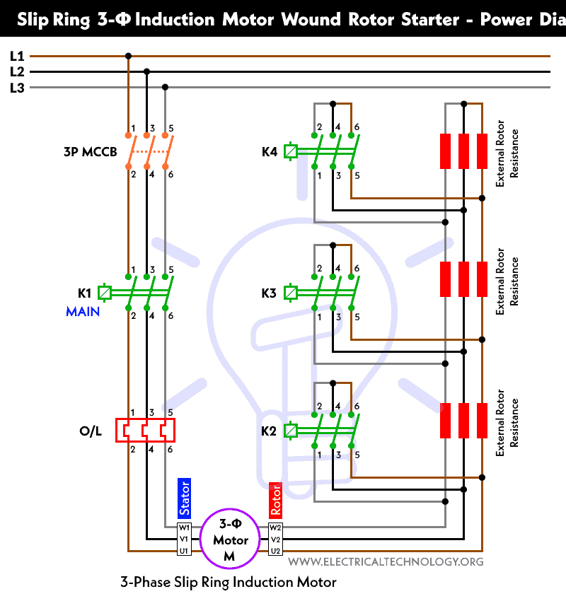
Wound rotor motors can be started with low inrush current by inserting high resistance into the rotor circuit. An interruption of the rotor circuit can result in a voltage transient eg rapid restrike or reclosure failure mode.

Wound Rotor Induction Motor Cool Electronics Mechatronics
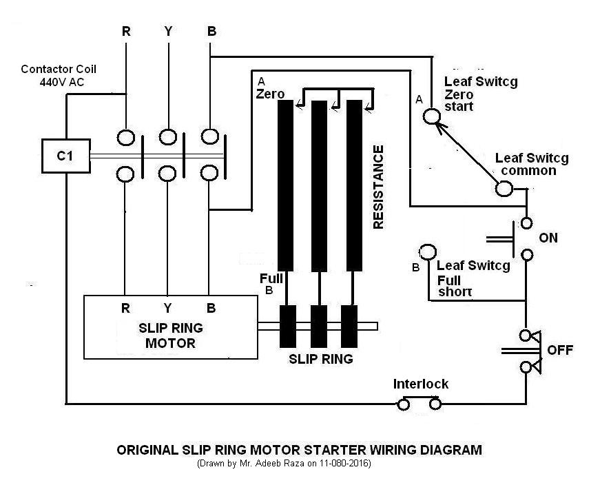
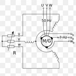
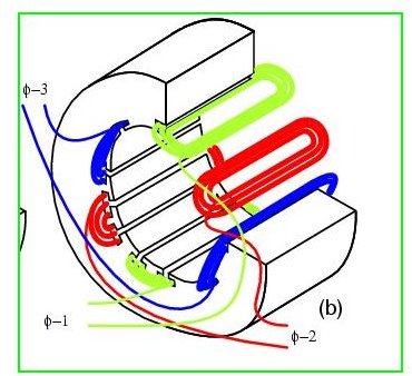
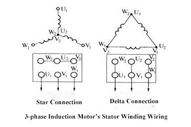
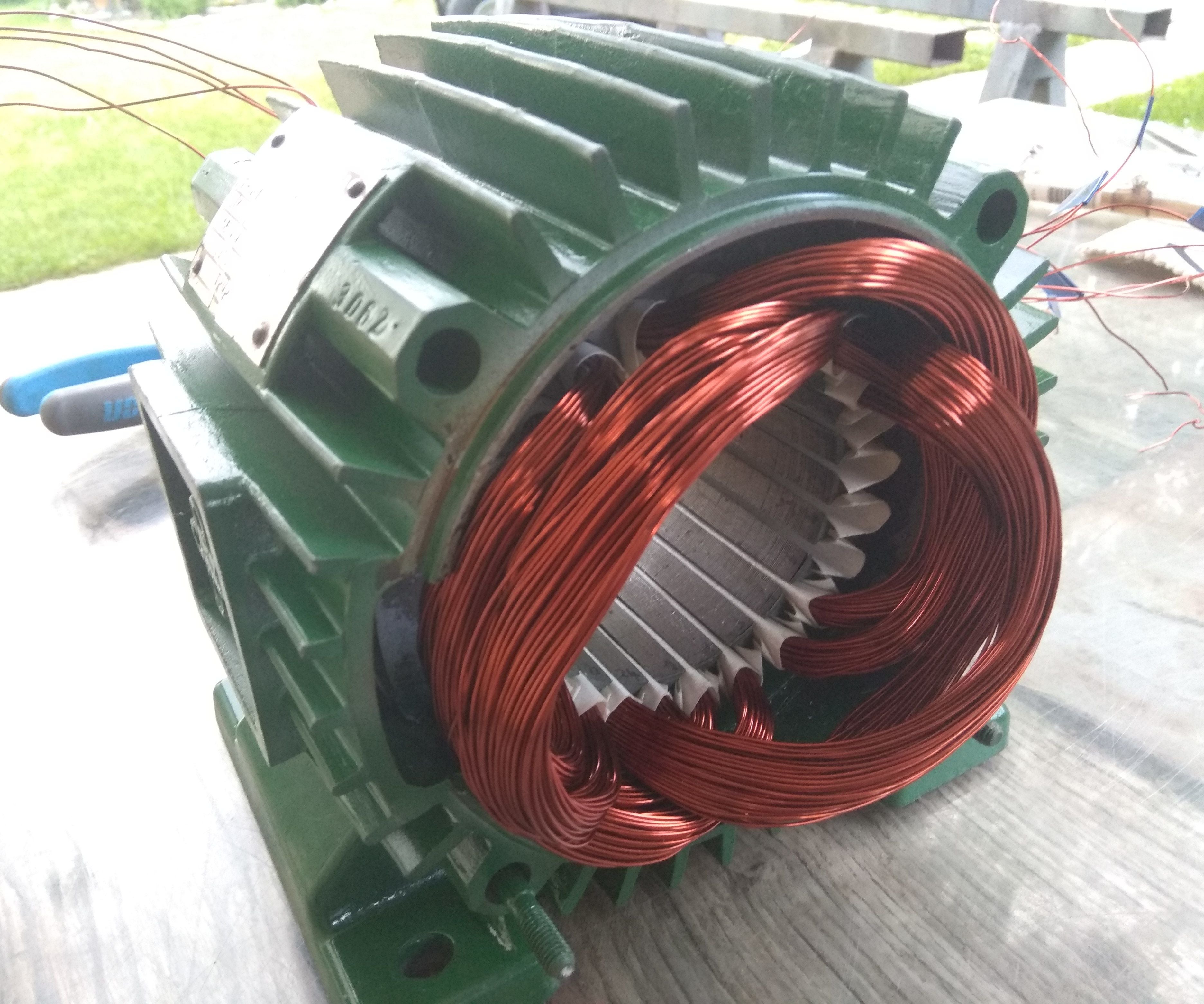
Wound rotor motor wiring diagram. That was the basic structure of stator now lets talk about rotor. Drawing the schematic diagram of autotransformer starter dol starter and star delta starter. Three phase wound rotor induction motor. A wound rotor induction motor has a stator like a squirrel cage induction motor but a rotor with insulated windings brought out via slip rings and brushes. Rotor of wound rotor induction motor. However no power is applied to the slip rings.
Another type is squirrel cage motor that has no wire winding and has no slip rings. In wound rotor motors the rotor is wound with wire similar to the stator with their terminal ends connected to 3 slip rings on the output shaft. The windings are accessible through slip rings. Are connected to 3 slip rings. First the entire rotor circuit must be con sidered. The self excited motors are further classified as shunt wound or shunt motor series wound or series motor and compound wound or compound motor.
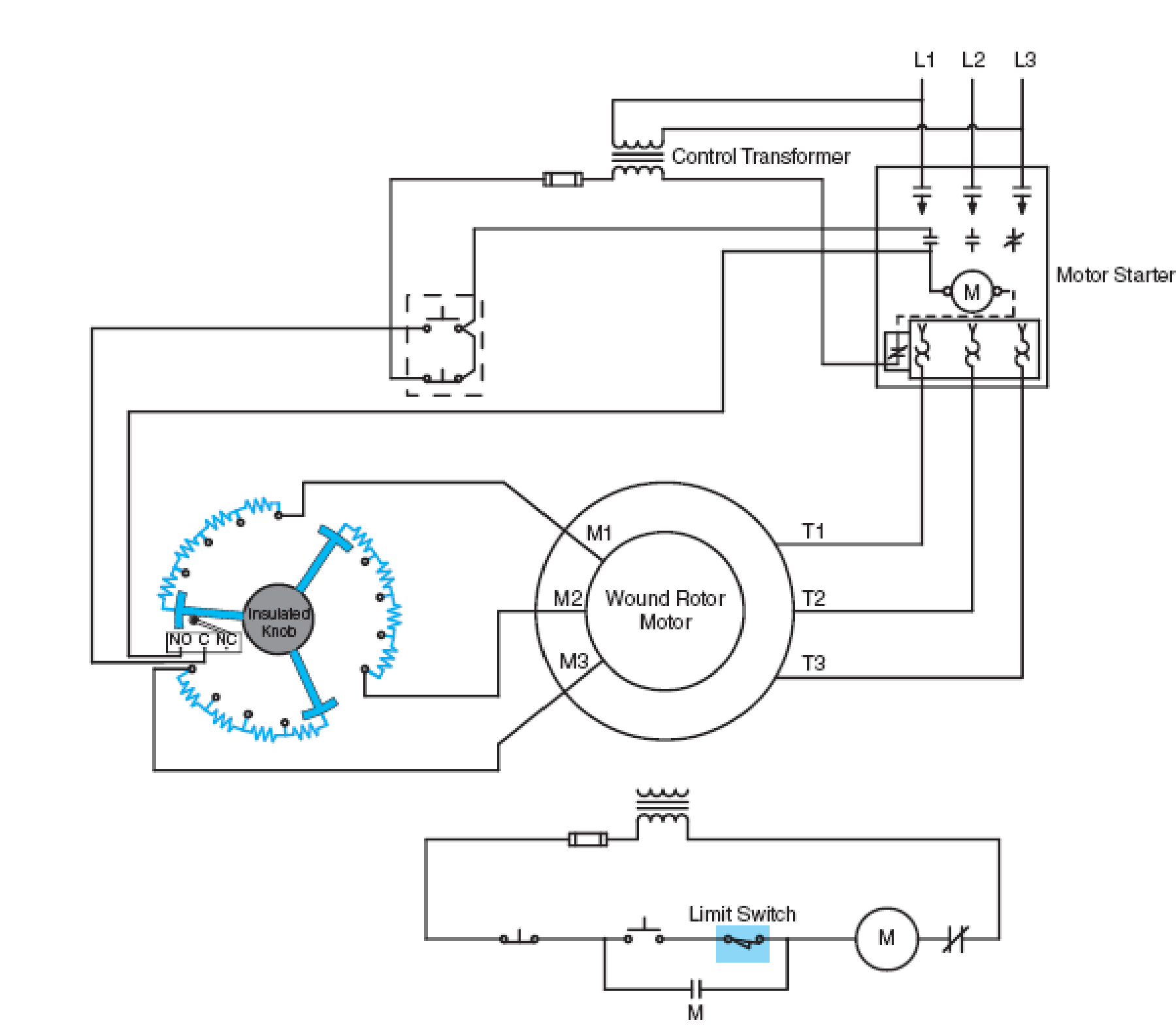
A typical wiring diagram of a combined faceplate starter and speed regulator for use in the rotor circuit of wound rotor induction motors is shown in fig. When a wound rotor motor fails there are several things to check to determine the underlying root cause of the failure. Most wound rotor motor rotor circuits use. Wound rotor induction motor wrim. In wound rotor induction motor the rotor has a 3 phase winding similar to stator winding. Starters of this type usually provide for a 50 speed reduction when the motor operates under full load at normal speed.
D motors should be put on pallets to prevent moisture. Types of dc motor a direct current motor dc is named according to the connection of the field winding with the armaturemainly there are two types of dc motors. Type of induction motor for ac in which the rotor has wire winding. These slip rings are attached to brushes and variable power resistor banks where operators can change the speed of the motor by varying the resistance through the rotor coils. Rotor is also cylindrical in shape and has slots to carry winding. Adjusting the resistance allows control of the speedtorque characteristic of the motor.
A wound rotor motor also known as slip ring rotor motor is a type of induction motor where the rotor windings are connected through slip rings to external resistance. 222 well protection motors should be well shielded from dust but under well ventilated circumstances. Typical wiring diagram for drum controller operation of ac. First one is separately excited dc motor and self excited dc motor. Their sole purpose is to allow resistance to be placed in series with the rotor windings while starting figure below. For those water cooling motors or using bearings with water cooling coils please make sure the water already dried off to prevent tube corrosion or danger of frost.
The winding is placed evenly on slots of the rotor. As the motor accelerates.
Gallery of Wound Rotor Motor Wiring Diagram