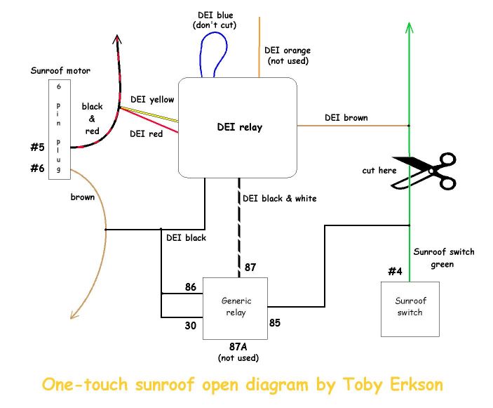
Peterbilt cruise control wiring diagram wiring diagram is a simplified customary pictorial representation of an electrical circuitit shows the components of the circuit as simplified shapes and the skill and signal friends along with the devices. Always make the relay and its connections difficult to discern from the factory wiring.
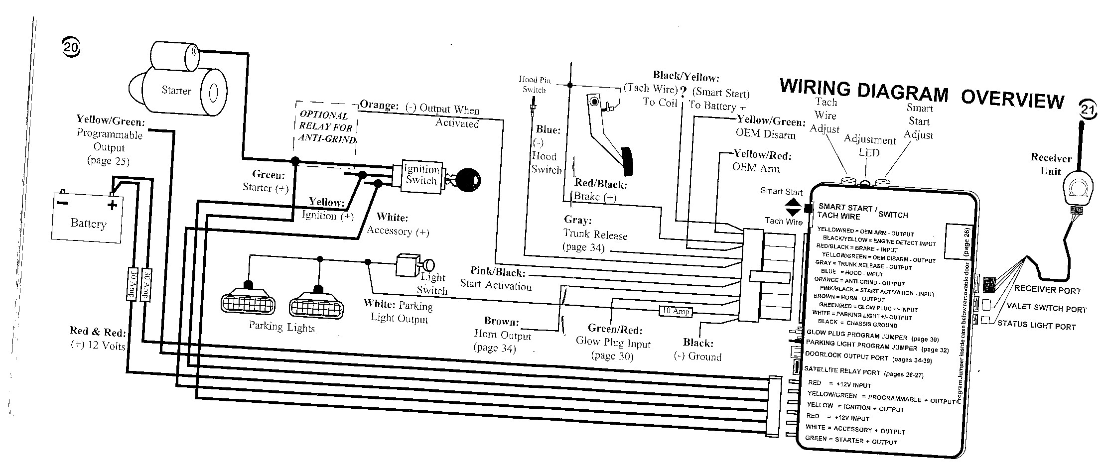
4105 Viper Remote Start Wiring Diagrams Diagram Base Website
Xcrs 500m wiring diagram. Free shipping for many products. Find many great new used options and get the best deals for dei xcrs 500m exteme capacity relay satellite bank viper python clifford at the best online prices at ebay. Xcrs harness h4 8 thick gauge wires relay pack these outputs are configurable by the installer when the module is flashed. Primary harness diagram 8 wire connection guide 9 plug in led and valetprogram switch 11 four pin shock sensor harness 11 new multiplex inputs bypassing sensor inputs 12 door lock wiring diagrams 12 15 transmitterreceiver learn routine 16 two vehicle operation with single transmitter 17 operating settings learn routine 18 feature. Directwire vehicle wiring database. Directeds state of the art directwire database provides detailed information on nearly 8000 vehicles.
The green wire is only required for starter kill and antigrind connections. Remote start ribbon harness wiring diagram remote start ribbon harness wiring diagram pinkwhite 200ma programmable ign2acc2 relay turn on yellow ignition input to alarm pink 200ma ignition relay turn on orange 200ma accessory relay turn on purple 200ma starter relay turn on orangeblack antigrindground when. Connpin color description h41 pinkwhite ignition 2 flex relay output h42 redwhite fused 30a ignition 2 flex relay input. Exposed yellow butt connectors do not look like factory parts and will not fool anyone. In this video i go over car alarm and remote start wiring in great detail. Dei xcrs 500m wiring diagram wiring diagram is a simplified gratifying pictorial representation of an electrical circuit.
For this reason routing the starter kill wires away from the steering column is recommended. View detailed directed product compatibility information for every vehicle and how to implement these solutions. Door lock wiring diagrams. It shows the components of the circuit as simplified shapes and the capacity and signal contacts with the devices. Be sure to also watch my 5 part series playlist on the installation job from start to finish.


