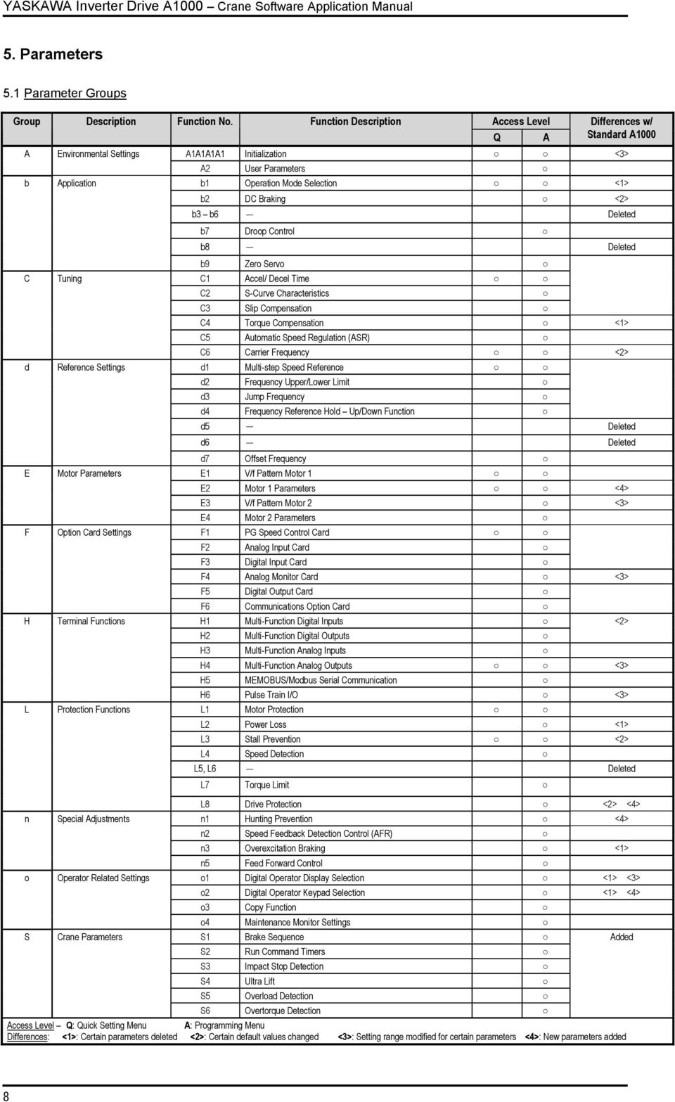
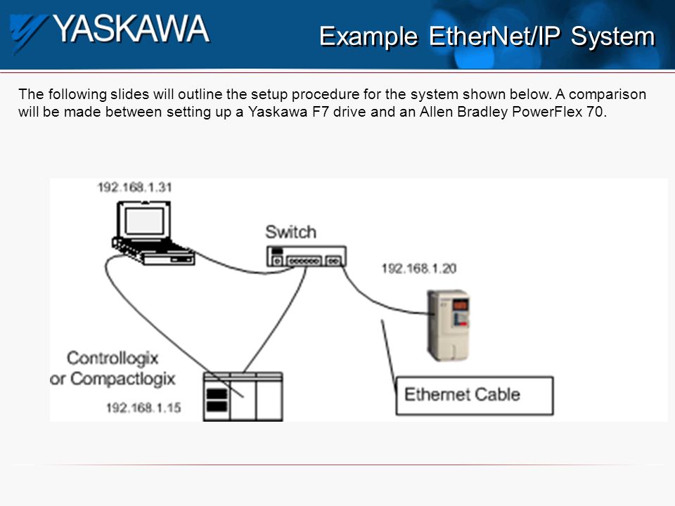
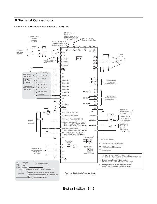
Schematic diagram of f7 drive. Dc drives yaskawa f7 technical manual.

Smarty Universal Automation Controller Bardac Drives
Yaskawa f7 wiring diagram. Drive safe off option 16 pages dc drives yaskawa f7 technical manual. Browse available downloads by product group and product line or by document type and sub type. Option card mechatrolink communications interface card. Primary delay filter the same value can not be set in h3 05 and h3 09. Wiring diagram for drivewizard and drivewizard plus cable to drive. Your supplier or yaskawa representative must be contacted when using leakage current circuit breaker in conjunction.
Option board models and specifications. Schematic diagram of f7 configured drive. These drives conform to the following standard. Related manuals for yaskawa f7. Yaskawa varispeed f7 pdf user manuals. Fig 213 field wiring diagram electrical installation 2 25 tel.
The shaded sections apply only to inverters with spec. Yaskawas z1000 variable speed drive is designed for building automation applications such as fans pumps and cooling towers through 500hp. Installing and wiring option boards. It may be helpful to copy this page. 86 755 8660. 12 500 hp.
The f7 series drives comply with the provisions of the low voltage directive 7323eec as amended by 9368eec. Diagrams drawings. Page 209 primary delay filter primary delay filter 2 is current input. View and download yaskawa varispeed f7 user manual online. Varispeed f7 recording equipment pdf manual download. The f7 drive was the industrial workhorse of adjustable frequency drives.
View online or download yaskawa varispeed f7 user manual instruction manual. Schematic diagram of f7 configured drive including options. Frequency reference varispeed f7 function block the following diagram shows the function block diagram of varispeed f7. It was intended to handle every conventional drive application found in the typical industrial manufacturing plant from simple variable torque pumping to sophisticated networked material handling. Schematic diagram of f7 drive showing terminations for inputs and outputs motor leads and power.


